
The design of a compact third-order fully canonical transversal microstrip bandpass filter (BPF) is described. It consists of two microstrip shorted stub loaded resonators (SSLR), where the fundamental mode is the even mode. By utilizing the resonance properties of the transversal filter and the introduction of source-load (S-L) coupling, the filter design incorporates two transmission zeros above and one below the passband. This improves passband selectivity and the rejection of unwanted signals above the passband.
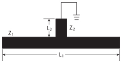
Figure 1 SSLR schematic.
In recent years, high-performance planar bandpass filters have found wide application in many RF/microwave circuits and systems. In these filters, transmission zeros at finite frequencies are needed to improve the passband selectivity and reject unwanted signals. For this purpose, a transversal filter is described by Rosenberg and Amari,1 where the signal couples to several resonators, providing more than one main path for the signal between the source and load. In the transversal filter, however, the source/load must couple to all resonators, while at the same time avoiding intercoupling between resonators. Transmission zeros can be realized due to counteraction among several main path signals. Stub loaded dual-mode filters with S-L coupling are special second-order fully canonical transversal filters.2-5,7 The practical implementation of a transversal filter, however, is difficult when the order is higher than two. Martinez-Mendoza et al.6 describe a third-order fully canonical transversal filter combining waveguide and microstrip techniques with two transmission zeros below and one above the passband, but the use of waveguide makes this filter much larger than conventional planar filters. Liao et al.7 describe how the extended-doublet filter can operate as a third-order transversal filter if intercoupling between the resonators is avoided; however, this structure has poor stopband performance. Zhou et al.8 describe a compact third-order transversal microstrip filter that incorporates a dual-mode open-loop resonator and a slot line resonator with S-L coupling. A disadvantage of having a slot line etched in the ground plane, however, is that the whole structure must be suspended far from other ground conductors for the slot resonator to be effective.
In this article, we discuss the design of a third-order fully canonical transversal microstrip BPF incorporating two SSLRs with S-L coupling. It has two transmission zeros above and one below the passband. This greatly improves the selectivity of the passband and the rejection of unwanted signals above the passband. We analyze the resonance characteristics of the SSLR using odd and even-mode analysis, design a transversal filter using SSLRs and verify the results through simulation and measurement. A 1.45 GHz three-order transversal microstrip BPF with 80 MHz bandwidth and 20 dB in-band return loss is designed. Measured results agree well with the simulations. The size of the filter is less than 0.092 λg × 0.12 λg, where λg is the guided wavelength on the substrate, making it smaller than the filters described in the references.
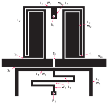
Figure 2 Layout of the third-order fully canonical transversal filter.
Analysis of the Shorted Stub Loaded Resonator
Figure 1 shows the schematic of the SSLR, which comprises a half-wavelength resonator and a shorted stub shunted at the midpoint. Z1, L1, Z2 and L2, denote the characteristic impedances and lengths of the half-wavelength resonator and shorted stub in the SSLR, respectively. Because the SSLR is symmetrical in structure, odd- and even-mode analysis can be used. The first resonant frequency is an even-mode. The resonant condition is given by
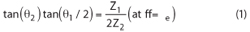
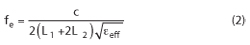
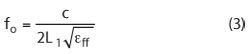
where θ1 and θ2 are the electrical lengths of the half-wavelength resonator in the SSLR and the shorted stub, respectively. fe is the even-mode resonant frequency of the SSLR. For the case where Z1 = 2Z2, the resonant frequency can be expressed as
For the odd-mode, the resonant characteristic is almost the same as that of the half-wavelength resonator, which is mainly determined by L1. The odd-mode resonant frequency of the SSLR is given by
By properly choosing the values of L1 and L2 using Equations 2 and 3, we can operate the even-mode and/or odd-mode of the SSLR together to define the passband of the filter. When L2 is slightly more than zero, the SSLR can be operated as a dual-mode resonator.
Design of the Third-Order Transversal Filter
The third-order transversal filter can be analyzed by using the theory of a second-order transversal filter. For a second-order transversal filter, one resonator is designed to work at odd resonance frequency (f0) and even resonance frequency (fe). The counteraction of signals in two main paths creates an inherent transmission zero at one side of the passband. An additional transmission zero can be created by introducing S-L coupling. For the dual-mode SSLR, external coupling for the odd-mode resonance is larger than for the even-mode resonance. Thus, for a third-order transversal filter with S-L capacitive coupling, the proper means to realize two transmission zeros above and one below the passband is to place one odd-mode resonant frequency between two even-mode resonant frequencies.
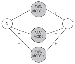
Figure 3 Corresponding coupling scheme of the third-order fully canonical transversal filter.
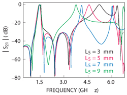
Figure 4 Simulated S21 of the filter for four values of L5.
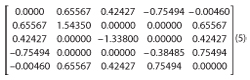
The layout of the filter is shown in Figure 2. It consists of two SSLRs with the S-L coupling. The SSLR on the top is a dual-mode resonator, and the other SSLR is an even-mode resonator. In the passband, the filter operates at f01, fe1 and fe2. The coupling scheme for a third-order transversal filter is shown in Figure 3. The signal is coupled to three modes at the same time, providing three main paths for the signal between the source and load, with no coupling between each of the modes. Three transmission zeros can be created near each band due to the three main path signals and S-L coupling counteraction. The coupling matrix can be written as
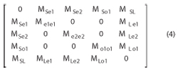
Since the three-order transversal filter exhibits symmetry, the relationship MSe1 = MLe1, MSe2 = MLe2 and MS01 = -ML01 holds. The gap between source and load (So) is introduced to provide the proper S-L coupling coefficient MSL for generating an additional zero. The location of the additional zero can be controlled by adjusting the value of So. The coupling coefficient MSo1 and MSe2 can be adjusted by changing S1 and S2. MSe1 can be adjusted by changing S1 and L6. Me1e1, Me2e2 and Mo1o1 can be adjusted with the dimensions of the SSLRs. As shown in Equation 3, the second odd-mode fo2 shifts lower in frequency as the length of half-wavelength resonator is increased.
Simulation and Measurement
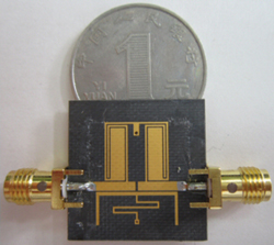
Figure 5 Photograph of the fabricated BPF.
To illustrate the procedure, a second-order generalized Chebyshev filter was designed with a passband return loss of 20 dB and three transmission zeros at normalized frequencies of the complex s-plane 6.86, 2.4 and –17.5. The 3 dB bandwidth is 80 MHz at the center frequency of 1.45 GHz. The filter exhibits the two transmission zeros above and one below the passband. The corresponding coupling coefficients are
S21 of the filter is simulated in Figure 4 for four values of L5, showing that the out-of-band spurious response can be controlled by the length of half-wavelength resonator of the even-mode SSLR.
The final dimensions of the fabricated filter are: L1 = 11 mm, L2 = 10 mm, L3 = 9 mm, L4 = 14 mm, L5 = 5 mm, L6 = 19.2 mm, L7 = 2.05 mm, W1 = 0.3 mm, W2 = 2.9 mm, W3 = 0.6 mm, W4 = 0.5 mm, W5 = 0.3 mm, W6 = 1 mm, Wo = 1.52 mm, R1 = 0.3 mm, R2 = 0.2 mm, So = 0.4 mm, S1 = 0.2 mm and S2 = 0.2 mm. The substrate has a relative dielectric constant of 2.2 and a thickness of 0.508 mm. Figure 5 is a photograph of the fabricated filter. Its physical dimensions are only about 14 × 17.5 mm, which corresponds to 0.092 λg × 0.12 λg, where lg is the guided wavelength at the center frequency 1.45 GHz.
Figure 6 shows the simulated and measured performance of the filter. The simulated/measured minimum insertion loss is 1.5 dB, and the simulated/measured minimum return loss is 20 dB/17 dB. The measured bandwidth is 75 MHz. Three transmission zeros are realized at 0.97, 1.6 and 1.7 GHz. The measured spurious mode is at 3.2 fo. The shift of the passband frequency and other discrepancies are attributed to fabrication tolerances.
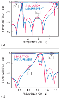
Figure 6 Measured and simulated frequency responses. Wideband response (a); Narrowband response (b).
Conclusion
A compact third-order fully canonical microstrip transversal filter incorporating a dual-mode SSLR and an even-mode SSLR with S-L capacitive coupling is described. Two transmission zeros above and one below the passband are created to improve the selectivity of the passband and reject unwanted signals. Measured results agree closely with simulation and validate the proposed structure and design method.
Acknowledgment
This work is supported by National Natural Science Foundation of China (Grant No.61101042) and the Fundamental Research Funds for the Central Universities (Grant No. ZYGX2009J043).
References
- U. Rosenberg and S. Amari, “Novel Coupling Schemes for Microwave Resonator Filters,” IEEE Transactions on Microwave Theory Techniques, Vol. 50, Issue 12, December 2002, pp. 2896-2902.
- L. Athukorala and D. Budimir, “Design of Compact Dual-Mode Microstrip Filters,” IEEE Transactions on Microwave Theory and Techniques, Vol. 58, Issue 11, November 2010, pp. 2888-2895.
- L. Athukorala and D. Budimir, “Compact Dual-Mode Open Loop Microstrip Resonators and Filters,” IEEE Microwave and Wireless Components Letters, Vol. 19, No. 11, November 2009, pp. 698-700.
- U. Rosenberg and S. Amari, “Novel Coupling Schemes for Microwave Resonator Filters,” IEEE Transactions on Microwave Theory and Techniques, Vol. 50, Issue 12, pp. 2896-2902.
- J.S. Hong, H. Shaman and Y.H. Chun, “Dual-Mode Microstrip Open-Loop Resonators and Filters,” IEEE Transactions on Microwave Theory and Techniques, Vol. 55, Issue 8, August 2007, pp. 1764-1769.
- M. Martinez-Mendoza, J.S. Gomez-Diaz, D. Canete-Rebenaque, J.L. Gomez-Tornero and A. Alvarez-Melcon, “Design of Bandpass Transversal Filters Employing a Novel Hybrid Structure,” IEEE Transactions on Microwave Theory and Techniques, Vol. 55, Issue 12, December 2007, pp. 2670-2678.
- C.K. Liao, P.L. Chi and C.Y. Chang, “Microstrip Realization of Generalized Chebyshev Filters with Box-Like Coupling Schemes,” IEEE Transactions on Microwave Theory and Techniques, Vol. 55, Issue 1, January 2007, pp. 147-153.
- M. Zhou, X. Tang and F. Xiao, “Compact Transversal Bandpass Filter Incorporating Microstrip Dual-Mode Open-Loop Resonator and Slot Line Resonator With Source-Load Coupling,” Microwave and Optical Technology Letters, Vol. 51, Issue 12, December 2009, pp. 2927-2929.