
A small (16.5 × 45 mm) forward-directional antenna covering the ISM bands of 2.45 and 5.8 GHz is designed for the next generation of multi-band compact handheld RFID readers. The antenna consists of a folded radiating copper strip fed by a CPW microstrip line and a ground plane. The copper strip produces surface waves at the operating frequencies that are reflected by the ground plane, producing radiation in the forward direction. Details of the antenna design and optimization are discussed by formulating closed-form equations for the resonances. Only 4 percent difference is found between the theory and simulation. The prototype exhibits 8.5 and 4 percent impedance bandwidths in the lower and upper operating bands, respectively. Measurements show forward-directed radiation patterns with good polarization purity, back radiation suppression and peak gain across the bands.
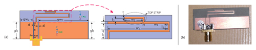
Figure 1 The geometry of the proposed antenna with an enlarged and elaborated view of the main radiating folded strip (a). Photograph of the fabricated prototype (b).
During the last decade, many techniques have been used to make handheld RFID devices more compact and multi-functional. It is common for a handheld RFID reader to employ a vertically radiating directional antenna at a right angle with the reader; thus the radiation literally becomes forward-directional to the reader.1 In this way, forward directional antennas can provide higher levels of compactness. Quasi-Yagi2 and folded dipole3 antennas are reported to have uni-directional radiation patterns taking the advantages of surface waves, but their balun structures have complex mechanisms to match the reflection coefficients of the driver elements and resonate at only one operating frequency. Recently, a microstrip-fed directional antenna was reported.4 Despite claims for long-range RFID coverage, it is printed double-sided (making it less compact and more difficult to integrate with solid-state active and passive components; and it, like the quasi-Yagi and folded dipole, resonates at only one operating frequency. The handheld multi-band antenna reported in reference 5 is also inappropriate for compact devices due to its large supporting ground plane. Although the Yagi antenna reported inreference 6 is uni-planar, it is difficult to incorporate circuitry due to its construction; and the feed transition of the multi-band quasi-Yagi-type antenna described in reference 7 requires a large area, which increases the antenna size significantly.
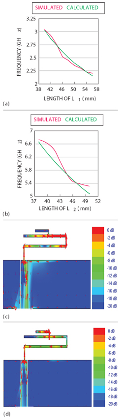
Figure 2 Comparison between the calculated and simulated resonating frequencies for different lengths of L1 (a) and L2 (b). Surface current distributions of the antenna at 2.45 GHz (c) and 5.8 GHz (d) showing frequency responses for different parts of antenna.
Inspired by the work reported in reference 4, this article describes a coplanar waveguide (CPW)-fed folded antenna with a small profile for handheld RFID reader applications. The antenna covers the ISM RFID bands of 2.45 GHz (2400 to 2483 MHz) and 5.8 GHz (5725 to 5875 MHz) with forward-directed radiation patterns in both bands. Details of the antenna design process and experimental results of the prototype are presented.
Antenna Configuration & Operation
The geometry and configuration of the uni-planar folded RFID antenna is shown in Figure 1(a) and a photograph of the fabricated prototype is presented in Figure 1(b). The radiating element is a folded strip of copper foil printed on a low cost TMM4 substrate with 35 µm thick copper cladding, a dielectric constant of 4.5 and a substrate thickness of 1.52 mm. The antenna substrate must be thick enough to allow a significant number of surface waves to be launched into the bare-slab portion of the antenna.1 A transmission line of width (fw) = 3 mm and length of (fl) = 10 mm is used to feed the folded strip. There is a gap of d = 0.3 mm between both sides of the transmission line and ground planes to form 50 Ω CPW line with the existing substrate. No metallization is applied on the reverse side of the substrate.
The longest path of the radiating folded strip defines the resonant frequency of the lower operating 2.45 GHz ISM band. Operation in the upper 5.8 GHz ISM band is achieved by the appropriate length and positioning of the top strip. Following this principle, the upper and lower resonances can be selected according to the following expressions:8
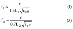
where the effective permittivity of the substrate is εeff ≈ (εr+1)/2 ≈ 2.75 and c is the speed of light. L1 = l1 + l2 + 2w1 and L2 = l1 + l2 + l3 + w1 + w2 + w3 + t are the dominant lengths of the folded strip for resonant frequencies fl and fu, respectively. The widths of all portions of the radiating strip are optimized to be t = 0.5 mm. Parametric analysis illustrates that, due to the importance of current density on the performance of this antenna, t should be much smaller than the thickness of the substrate. In order to verify accuracy of the formulas for the resonating frequencies, the dominant lengths are varied while keeping the other parameters unchanged and the resonating frequencies are calculated using equations 1 and 2. The results are compared with those produced by the full-wave, method-of-moment based electromagnetic simulator Zeland IE3D. The comparison, shown in Figures 2(a) and (b), illustrates that the difference between the simulated and calculated values is only around 4 percent for both operating bands, confirming that the equations provide quite an accurate mathematical estimation for the required lengths of L1 and L2.
Another way to understand the operating principle of the antenna is by studying the excited surface current distribution, shown in Figures 2(c) and (d). From the strong current distribution observed in the folded strip, it is evident that the surface waves at both 2.45 and 5.8 GHz are generated from this region. Also at each resonant frequency, the current density is higher on the parts of the folded strip whose dimensions are assumed to govern that particular frequency. The lengths L1 and L2 might also be determined through this observation.
The ground plane does not carry significant current components. The currents flowing on the edges of ground plane are out of phase with the current on the feed strip in close proximity and thus their radiating effects are mostly nullified. This means that the ground plane does not actively participate in creating the resonances; it acts more likely as a reflector, forcing the electromagnetic energy developed by the surface waves, to be launched into the forward direction.2 The ground plane dimensions, therefore, are critical for the directivity of the antenna, especially since there are two discrete operating bands. The dimensions of the ground planes are gw1 = 32.7 mm, gl1 = 10 mm and gw2 = 8.7 mm.
The folding distances l1, l2 and l3 have a prominent effect on the forward-directivity of the antenna. To obtain the best performance, these are optimized with the values l1 = 3.15 mm, l2 = 1.6 mm and l3 = 0.6 mm. Note that the folding distances are comparable to the substrate thickness of the substrate or its multiplier. Other optimized values are: w1 = 21.7 mm, w2 = 9 mm and w3 = 6.7 mm. The overall dimensions of the antenna are approximately 0.13λ0 × 0.36λ0 (16.5 × 45 mm), where λ0 is the corresponding free space wavelength at lowest resonance 2.45 GHz.
Simulation & Measurement
An antenna prototype with the optimized parameters was fabricated and tested using the Agilent E8357A vector network analyzer. Figure 3 shows good agreement between the simulated and measured return loss. Its impedance bandwidth (return loss greater than 10 dB) for the 2.45 GHz band is 210 MHz (2.36 to 2.57 GHz) and for the 5.8 GHz band is 230 MHz (5.69 to 5.92 GHz). These are equivalent to 8.5 and 4 percent fractional impedance bandwidths with respect to the center frequencies of 2.47 and 5.81 GHz. This satisfies the dual ISM-band (2.45/5.8 GHz) requirement for RFID applications. The third graph of Figure 3 also shows that both resonating frequencies can be individually tuned.
The normalized E- (XY) and H- (YZ) plane radiation patterns of the antenna at 2.45 and 5.8 GHz (see Figure 4) are forward-directed, with the backward radiation suppressed by around 9 dB at 2.45 GHz and 22 dB at 5.8 GHz. The cross-polarization levels for both E- and H- planes are less than –12 dB. The patterns are well behaved and directional with high polarization purity in the forward direction and good front-to-back ratio, which is an important characteristic for RFID handheld readers.3 These characteristics are maintained across both bands. Maximum gains of 3.1 and 3 dBi are achieved in the lower and upper bands respectively, with a less than 0.5 dBi gain variation.
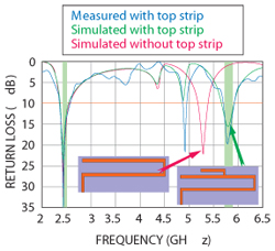
Figure 3 Measured and simulated return loss of the dual-band antenna.
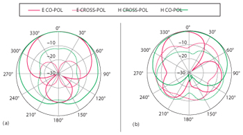
Figure 4 Measured radiation patterns of the proposed antenna at E- (XY) and H- (YZ) planes at 2.45 (a) and 5.8 GHz (b).
Conclusion
A new CPW-fed folded RFID antenna is described. The antenna design process is discussed in detail, explaining the antenna operating principles and providing equations that govern the dimensions. A prototype antenna demonstrates an impedance bandwidth broad enough to cover both the 2.45 and 5.8 GHz ISM bands, and has a forward-directed radiation pattern with good polarization purity, front-to-back ratio and peak gain. With these characteristics, the proposed antenna should find wide use in multi-band compact handheld RFID readers.
References
- A.T. Mobashsher, M.T. Islam and N. Misran, “A Novel High Gain Dual Band Antenna for RFID Reader Applications,” IEEE Antennas and Wireless Propagation Letters, Vol. 9, July 2010, pp. 653-656.
- K.M., K.H. Leong, Y. Qian and T. Itoh, “Surface Wave Enhanced Broadband Planar Antenna for Wireless Applications,” IEEE Microwave and Wireless Components Letters, Vol. 11, February 2001, pp. 62-64.
- R.C. Hua and T.G. Ma, “A Printed Dipole Antenna for Ultra High Frequency Radio Frequency Identification (RFID) Handheld Reader,” IEEE Transaction on Antennas and Propagation, Vol. 55, Issue 12, December 2007, pp. 3742-3746.
- X. Yang, Y.Z. Yin, W. Hu and G. Zhao, “Compact Printed Double-Folded Inverted-L Antenna for Long-Range RFID Handheld Reader,” Electronics Letters, Vol. 46, Issue 17, August 2010, pp. 1179-1181.
- A.T. Mobashsher, M.T. Islam and N. Misran, “Triple Band RFID Reader Antenna for Handheld Applications,” Microwave and Optical Technology Letters, Vol. 53, Issue 7, July 2011, pp. 1629-1632.
- P. V. Nikitin and K.V.S. Rao, “Compact Yagi Antenna for Handheld UHF RFID Reader,” IEEE Antennas and Propagation Society International Symposium, July 2010, pp. 1-4.
- Y. Ding, Y.C. Jiao, P. Fei, B. Li and Q.T. Zhang, “Design of a Multiband Quasi-Yagi-Type Antenna With CPW-to-CPS Transition,” IEEE Antennas and Wireless Propagation Letters, Vol. 10, October 2011, pp. 1120-1123.
- K.G. Thomas and M. Sreenivasan, “Compact Triple-Band Antenna for WLAN/WiMAX Applications,” Electronics Letters, Vol. 45, Issue 16, July 2009, pp. 811-813.
Ahmed Toaha Mobashsher received his bachelor of science degree in Electrical and Electronic Engineering from Chittagong University of Engineering and Technology, Chittagong, Bangladesh, in 2008 and his master’s degree in 2011 from the Universiti Kebangsaan, Malaysia (UKM). He worked as a research assistant and then as a researcher at the Institute of Space Science (ANGKASA) of UKM and as a lecturer in the Department of Electrical & Electronic Engineering of Southern University, Bangladesh. He was also a Lecturer in the Department of Electrical and Computer Engineering at King Abdualaziz University, Saudi Arabia during 2011-2012. He is currently completing his Ph.D. degree at the University of Queensland. His research interests include antenna development for RFID readers, compact, multi-band and wideband antennas, notched ultra-wideband antennas, metamaterial antennas and antenna miniaturization.
Rabah W. Aldhaheri received his bachelor of science degree from Riyadh (currently, King Saud) University in 1975, his master’s degree from Ohio University, in 1981, and his Ph.D. degree from Michigan State University in 1988, all in electrical engineering. From 1976 to 1981, he was with the P.T.T. Ministry, Jeddah, Saudi Arabia as an electrical engineer and then as a director of the Microwave and Multiplex Stations. In 1981, he joined King Abdulaziz University as a lecturer in the department of electrical and computer engineering. He is currently a full professor in the same department. Aldhaheri has held visiting research scholar positions with Michigan State University during 1994-1995, and Queensland University of Technology (QUT) in Brisbane, Australia in 2000. His research interests include digital signal processing with application to filter design and biometric recognition, microelectronics devices and wireless communications. He is an associate editor of the Journal of Applied Sciences