

 Watch Video
Fraunhofer HHI Cooperative Communication Strategies for Distributed Antennas
The rapacious demand for wireless data has spurred researchers to search for new technologies to expand wireless data capacity and network capability. Industry experts universally agree that even with current and planned infrastructure rollouts, data demand will continue to outpace capacity and the debate has shifted from “if” to “when” this event will occur. Wireless service providers plan to furiously upgrade their networks to 4G LTE, LTE-Advanced (LTE-A) and beyond, introducing new innovations such as small cells, heterogeneous networks, and carrier aggregation along the 3GPP roadmap. However, it is clear that the current technology trajectory produces a capacity slope that is still flatter than the demand line. Embracing the challenge, the 3GPP standards body recently adopted a goal of increasing data capacity “1000× by 2020” acknowledging the need for evolutionary or revolutionary ideas.
One such concept entails the deployment of base stations with very large scale antenna arrays encompassing perhaps hundreds of transceiver elements. This concept is referred to as Massive MIMO.1 Indeed, Massive MIMO departs from current network topologies and could be a key to solving our wireless data challenges; however, another interesting question is posed through the process of understanding the effectiveness and/or feasibility of Massive MIMO for wide spread deployment – just how does one go about creating a prototype to truly see whether it will work? After all, creating a prototype with hundreds of antenna elements creates several engineering challenges not the least of which include cost and time.
MIMO Background
MIMO relies on multipath to enhance the reliability and the effective data rate of a wireless data link using multiple streams typically through several separate antennas. Multipath propagation, a formidable challenge to robust communication systems, is actually exploited with MIMO using a variety of techniques including space-time coding and/or spatial diversity.2 The 4G cellular standard LTE-A specifies a maximum of eight antennas for use in a MIMO configuration. The IEEE 802.11n/ac standards and the actual commercialization of those standards are the predominant use cases of MIMO in practice.
Basically, more antennas yield more degrees of freedom of the propagation channel delivering improved performance in terms of data rate and/or link reliability. However, the overall data rate is still constrained by the Shannon-Hartley theorem. In a network with multiple users, one way to increase the overall network throughput is through multi-user MIMO (MU-MIMO), where multiple users can simultaneously access the same time-frequency resource, but it is separated through the multiple “spatial dimensions” created by multiple antennas.
More Antennas, More Capacity, Enhanced Reliability
Scaling up MU-MIMO to a large scale, classified as Massive MIMO, potentially offers higher network capacity, better reliability and increased energy efficiency of the Massive MIMO base station by lowering the overall transmitted power in a cell or served region. Theoretically, the transmitted power per antenna could be less than the transmitted power of a single antenna serving a designated cell or region with the same data rate. That is, the overall power given by
PTotMM ~ PT NT
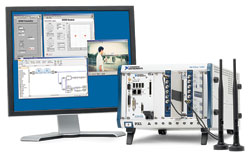
Figure 1 Two-antenna MIMO transceiver.
where PTotMM is the total transmitted power per region, PT is the power per antenna, NT is the number of transmit antennas, and PTotMM is less than PTot of a single antenna system. A Massive MIMO cellular topology could potentially reduce the overall transmitted power in a sectorized region compared to the power needed in a single antenna system to achieve the same reliability and/or throughput because of the increased capability of the Massive MIMO base station to focus its emitted energy to the desired users through its increase in degrees of freedom. In addition, the probability of the correct bits being transmitted from a transmitter to a receiver increases when multiple antennas are deployed, since
Link Outage Probability ~ 1 / SNR NT NR
where SNR is the signal to noise ratio, NR is the number of receive antennas and NT is the number of transmit antennas. As the number of antennas increase in a system, the probability of a link outage decreases thus increasing the communications link reliability.2
Large scale MIMO antenna arrays build on the fundamental concepts presented here, behind the theory that antenna deployments in the hundreds scale to realize better efficiencies than current MIMO point-to-point deployments. Specifically, with hundreds of antennas, the antenna aperture and deployment grid will have a much finer resolution. Combined with beamforming, the antenna lobes can be more finely controlled to reduce power in the channel.
Massive MIMO systems are not without their challenges. One challenge includes finding a way to communicate the channel state information from the receiver to the transmitter for precoding. With hundreds of antennas, the number of pilot signals needed to derive the channel state is really not practical. Massive MIMO in its current incarnation is hence only practical in a time-division-duplexed (TDD) system which relies on the reciprocity of the channel, but to determine the feasibility of this approach more research is needed. Some initial research has also proposed that the thermal noise in the system is less of a concern with so many antennas, and the impact of interferers becomes more of an issue. These challenges and others can be explored with real world waveforms once a working prototype has been developed.
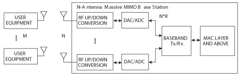
Figure 2 M-user, N-antenna Massive MIMO system.
Prototyping a Massive MIMO System
The task of prototyping a Massive MIMO system requires a lot of up front work to carefully and properly design an actual working system. Most researchers may find that even prototyping a minimally configured two antenna MIMO transceiver system can be challenging (see Figure 1). To begin the task of designing a Massive MIMO prototype, let’s first sketch a diagram of the system (see Figure 2). For the purposes of this exercise, we will use N number of antenna elements at the base station to be 128 to achieve a 128 × 128 MIMO configuration. The configuration does assume M mobile users using SISO antennas.
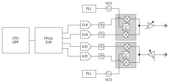
Figure 3 Typical 1×1 software defined radio architecture.
There are many items to consider when designing a large scale MIMO system, including RF system parameters such as transmit power, adjacent channel interference, conformance to spectrum mask and so on. However, a key parameter to consider in a large scale MIMO system is the digital data throughput to and from each antenna. From Figure 2, one of the most challenging aspects of the system is aggregating all of the received samples into a common processing subsystem. Unlike simple transmit and receive communications using a SISO radio, Massive MIMO requires high speed data throughput between transmit and receive elements and the baseband – an order of magnitude higher than today’s currently deployed systems.
Processing the data streams in a distributed fashion to the nodes located close to the antenna is an option, but in order to recover the received signals from, or effectively precoding the signals to the different users, the data streams from each antenna must be aggregated at a common location in order to extract the best performance. Taking a closer look at the throughput and data requirements, we break down the system into their fundamental elements. Thus, we can quantify the data rates into the actual building of the prototype and explore tradeoffs that can impact system design, integration, power and ultimately cost.
Baseline System Parameters
A typical SISO radio is depicted in Figure 3. In this diagram, the RF signal is downconverted or mixed down, filtered and then amplified before being converted to digital data. The transmit operation uses the reverse flow. A Massive MIMO system encompasses hundreds of these fundamental SISO elements.
In order to use off-the-shelf equipment to lower cost and expedite prototype development, it is assumed that each In Phase (I) and Quadrature (Q) sample is 16 bits. The number of bits determines dynamic range and in effect may be more than enough for the prototype. Fewer bits of resolution can reduce the data throughput significantly especially when aggregating so many channels. Although 16 bits increase the data path and ultimately the data throughput requirements – more bits lead to wider data paths and increased data throughput requirements – off-the-shelf components and programming architectures handle 16-bit samples easily without customization.
Next consider the sampling rate. Each analog-to-digital converter (ADC) in the receive chain must sample the downconverted waveform at a rate greater than the bandwidth of the channel consistent with the Nyquist theorem. This example will focus on using LTE as a baseline, a common cellular scenario, where each converter samples the received waveform at a sample rate of 30.72 MS/s. In fact, the converter may oversample the signal to increase resolution but may increase the signal processing to convert the data rate to a data stream that a standard signal processing block can accept. The data throughput can be derived using the following equation:
(2 samples) (16 bits per sample or 2 bytes/s) (sample rate)
For the example described above:
(2 samples) (2 bytes/s) (30.72) = 122.88 MB/s
For the example system description, the aggregate data throughput for one channel equals 122.88 MB/s.
To scale to a Massive MIMO system, the effective rate can be calculated as follows:
Total System Throughput (TST) = (Throughput rate/channel) (number of antennas)
TST = (122.88 MB/s) (128)
TST = 15.7 GB/s
Thus, if all channels were either transmitted or received simultaneously, then the data throughput to the central processing system would be 15.7 GB/s. In addition, aggregating all of this data into the central processing system requires a processing engine capable of accepting this massive amount of data and the capacity to further process the data in order to produce a communication link.
Two challenges are revealed through this brief analysis. First, there are few, if any, low-cost commercially-available technologies that can address these requirements. Second, the data rate for the prototype requires exploration of alternative partitioning of the signal processing chains including distributed and parallel implementations.
Reviewing the available technologies for prototyping, we present a brief survey of high speed serial buses that potentially can be used as the data framework for constructing the Massive MIMO prototype.
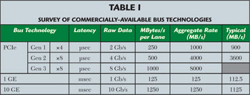
Table 1 presents an overview of some high-speed commercially-available bus technologies today. There are other buses, of course, but this table presents a guideline of many of the popular buses today that are open standard and not proprietary. In addition, these bus technologies are used in many of today’s modular architectures such as PXIe, which is fundamentally based on the PCIe standard.
One specification that should be considered is latency. Latency describes the turnaround time between a transmit and receive operation. If the prototype is for a unidirectional link, then latency is of less importance. However, for a true TDD Massive MIMO prototype, latency must be considered as it is critical for the turnaround time to be shorter than the coherence time of the wireless channel so that the downlink precoding is not based on outdated channel information. The latency specification given here is an approximation. However, in general, Ethernet latency is non-deterministic and can vary significantly. On the other hand, Ethernet implementations tend to be lower cost.
It should be noted that PCIe Gen 3 implementations are just now appearing on the market and measured actual throughput data was not available. It should also be noted that although maximum/peak data rates are widely available, typical implementations where the bus is actually implemented vary due to cost, IP core size and power. The typical numbers are provided as a guideline as few, if any, implementations will achieve the maximum published rates.
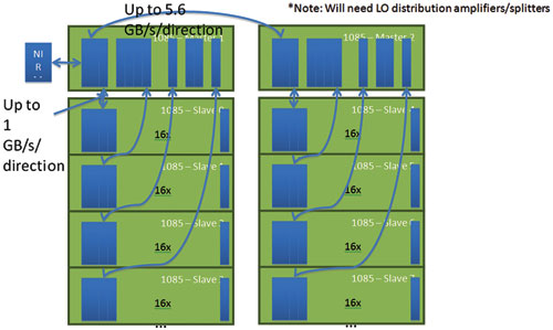
Figure 4 Example implementation using PXIe.
Figure 4 shows an example system configuration using PXIe. In this configuration, a total of 10 chassis are used to achieve a 128-antenna Massive MIMO system. The system employs two “Master” chassis to aggregate the data and eight slave chassis housing 128 transceivers (NI 5791 RF transceiver) capable of transmitting and receiving in the cellular bands. The data backbone uses PCI Express Gen 2 × 8 to easily capture and transmit 20 MHz of RF bandwidth data with appropriate partitioning.3,4
Conclusion
Massive MIMO is just one of many new technologies being explored for 5G communications. However, with new technology, a bottleneck between theory and standardization can be prototyping. Massive MIMO’s system parameters push the envelope in terms of requirements to actually test the theory and expedite commercialization. Although there are many commercially available technologies, PCI express appears to have an optimal combination of sufficient data throughput and low latency to truly test the effectiveness of Massive MIMO in practice. Of course building a complete system requires further work, but one of the central challenges to building such a prototype pertains to the careful analysis of the data throughput, latency and signal processing which are addressed in this article.
References
- F. Rusek, D. Persson, B.K. Lau, E.G. Larsson, T.L. Marzetta, O. Edfors and F. Tufvesson, Scaling up MIMO: Opportunities and Challenges with Very Large Arrays, IEEE Signal Process Mag., Vol. 3 No. 1, pp. 40-46, Jan. 2013.
- A. Paulraj, R. Nabar and D. Gore, Introduction to Space-Time Communications. Cambridge: Cambridge University Press, 2003.
- www.pcisig.com/specifications/pciexpress/resources/PCIe_3_0_External_FAQ_Nereus.pdf.
- www.xilinx.com/technology/protocols/pciexpress.htm