
Today’s airline passengers expect to have easy access to internet servers, email and in-flight entertainment while airborne. GORE™ Leaky Feeder Antennas improve signal propagation while potentially reducing the amount of hardware required on the plane. These antennas provide reliable connectivity to different wireless systems, including picocells for mobile phone coverage and access points for airborne Wi-Fi. Ideal for both wide-body and single-aisle passenger aircraft, these antennas significantly reduce dead spots, enabling passengers to connect to wireless networks throughout the cabin. Typical applications for the leaky feeder antennas include Wi-Fi 801.11 a/b/g/n/ac and WiMAX as well as connectivity to Bluetooth, GSM and MMS.
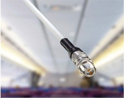
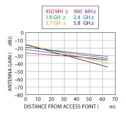
Figure 1 Antenna Gain: GORE™ Leaky Feeder Antennas 355.
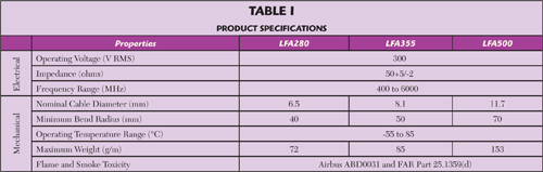
With a single antenna installed along the length of the cabin, passengers can access wireless networks from their laptops, tablets, mobile phones and in-flight entertainment systems regardless of their location in the cabin. These antennas dramatically reduce dead spots because of the proprietary technology that maintains excellent antenna gain and coupling loss over a broad range of frequencies and antenna lengths (see Figures 1 to 6) as measured according to IEC 61196-4, Free Space Method. GORE Leaky Feeder Antennas provide consistent connectivity across a broad frequency range — from 400 MHz up to 6 GHz — making the antennas compatible with numerous communication standards (see Table 1).
Integrated Hardware Runs Multiple Protocols
Wireless technology used in aircraft generally requires separate antennas for each wireless protocol. However, the leaky feeder antennas enable integrated hardware to run multiple protocols through a single antenna, reducing the quantity of access points necessary to ensure signal coverage. This reduces the cost for wireless access as well as reducing exposure to wireless radiation.
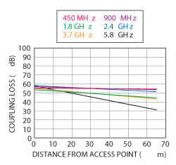
Figure 2 Coupling Loss: GORE™ Leaky Feeder Antennas 355.
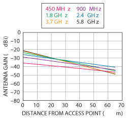
Figure 3 Antenna Gain: GORE™ Leaky Feeder Antennas 280.
These lightweight antennas reduce equipment costs by offering a single solution that provides connectivity for a variety of electronic devices. Because of their durable construction, these leaky feeder antennas do not require any maintenance for the life of the aircraft, further reducing operating costs. They offer easy installation for new production as well as retrofit applications in both single-aisle and wide-body aircraft.
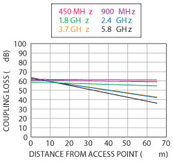
Figure 4 Coupling Loss: GORE™ Leaky Feeder Antennas 280.
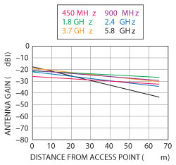
Figure 5 Antenna Gain: GORE™ Leaky Feeder Antennas 500.
Durable, Flame-Retardant Construction
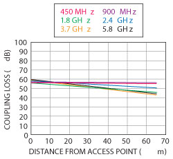
Figure 6 Coupling Loss: GORE™ Leaky Feeder Antennas 500.
The engineered fluoropolymers used in the construction of GORETM Leaky Feeder Antennas are inherently flame-retardant. They meet Airbus ABD0031 and FAR Part 25.1359(d) specifications for flame and smoke toxicity, ensuring reliable flame protection without the need for additional flame retardants. These materials are also resistant to abrasion and cut-through, reducing the potential for damage during installation.
GORETM Leaky Feeder Antennas make possible new in-flight systems that allow aircraft passengers to use their own mobile phones and other electronic devices. They can make calls, send texts and access the internet just like they do when sitting in their offices: simply pick up the device and start using it.
W. L. Gore & Associates Inc., Landenberg, PA,
www.gore.com/electronics