
Exponential growth in our appetite for information underscores the need for communications systems capable of transmitting, receiving and processing of ever-increasing data at higher data rates. Since system capacity is limited by bandwidth and channel capacity, current approaches for addressing this challenge include systems with multi-input to multi-output capabilities. Given the inherent relationship between cost and scaling in these architectures, a more effective approach to meet present and future needs is the use of low noise carriers at microwave, mm-wave and higher frequency.
Reference oscillators generate the carrier waves in systems that receive and transmit information. The ideal carrier signal is a pure sinusoid, with a frequency many times larger than the information rate, which is modulated on it. This is because the capacity or the information bandwidth of a system is a fraction of its carrier’s frequency. Furthermore, any noise that spoils the “spectral purity” of the carrier’s sinusoidal signal further limits this capacity. Thus, reference oscillators with higher spectral purity at higher frequencies are required to meet the demands of high throughput information links. The same requirements pertain to high performance test and measurement systems, and high performance radar, which have similar needs for high frequency and high spectral purity.
Optical Versus Other Oscillator Technologies
Traditionally, quartz oscillators have been used for high spectral purity carriers.1 Indeed, today’s high performance quartz oscillators provide unmatched spectral purity, but for frequencies at or below a few hundred MHz. In systems where data rates exceed these frequencies, high quality quartz oscillators cannot be used directly; rather, the oscillator frequency must be multiplied to accommodate the data rate. Frequency multiplication is widely used, but at the penalty of system complexity, as well as the multiplication of oscillator noise. Other types of electronic oscillators producing signals at higher frequencies (such as SAW oscillators, dielectric resonator oscillators [DRO], and Gunn oscillators) have relatively high associated noise. This is because oscillators essentially consist of a narrowband high Q element (such as a resonator) that filters the noise generated by an amplifier within a feedback loop, resulting in self-sustained oscillation. The high Q element in conventional oscillators typically determines both the frequency of operation and the achievable spectral purity. Since a resonator’s size (volume) decreases with increasing frequency, high frequency electronic resonators have lower Q, resulting in lower oscillator spectral purity.
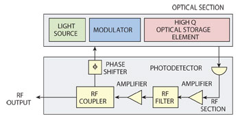
Figure 1 Schematic diagram of the generic Opto-Electronic Oscillator.
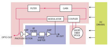
Figure 2 The Coupled Opto-Electronic Oscillator.
Photonic oscillators do not have these inherent limitations. Since microwave, mm-wave and even THz signals are a fraction of the frequency of light, the use of optical elements minimizes loss with increased frequency. Furthermore, optical waveguides and resonators can be produced with extremely low loss, providing very high Q elements for photonic oscillators. Finally, as described in this article, the extremely high Q of certain optical resonators enables the emergence of nonlinearities that can be put to advantage for generations of reference signals.
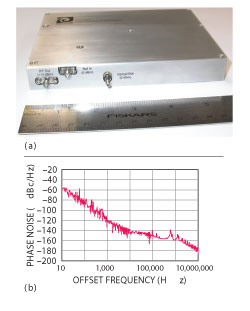
Figure 3 Packaged COEO (a) and its phase noise spectrum at 10 GHz (b).
Opto-Electronic Oscillator
The most widely known photonic oscillator is the opto-electronic oscillator (OEO).2 The OEO is based on a feedback loop that converts modulated light from a laser to RF (microwave/mm-wave) frequency. In its generic form (see Figure 1), the modulated light is generated by direct modulation of the laser current, or by use of an amplitude, or phase modulator. The modulated light passes through a high Q energy storage element, before it is detected by a high frequency photodetector (PD). The output of the PD is amplified, adjusted for phase, and fed back to the modulator to complete the loop. The high Q element in the optical segment of the loop can be a long fiber delay, in which case the center frequency of a filter in the electronic segment of the loop determines the frequency of operation. Alternatively, the high Q energy storage element may be an optical resonator, in which case its free spectral range (FSR) sets the frequency of the oscillator. The feedback loop consists of electronic and optical components, which can be interchanged in the optical or electrical segment of the loop. In its most common configuration the gain elements, the filter and the phase shifter are included in the RF segment.
OEO is a versatile architecture that allows for the interchange of components in the optical loop with their electronic counterparts, or vice versa. For example, the needed gain in the loop can be provided with either an electronic amplifier or an optical amplifier. The same is true for the element that adjusts the phase in the loop to keep the oscillator stable. Furthermore, since the center frequency of the filter determines the operation frequency, any desired frequency supported by the bandwidth of the modulator, the gain elements, and the PD may be obtained. Conveniently, the use of a tunable filter can produce a tunable OEO with the unique feature of same spectral purity for any frequency within the bandwidth.3 More importantly, even the light source can be inside the loop. This may be accomplished by using an optical amplifier with its output connected to its input, and by coupling it to the modulator as part of the optical segment of the OEO. This latter scheme is known as a coupled opto-electronic oscillator, or COEO (see Figure 2 and Figure 3), and includes the benefit of an active element to multiply the Q of the oscillator.4 In the configuration shown in Figure 2, the optical signal is produced in the upper loop with an optical gain. The optical loop and the RF loop are coupled through the modulator.
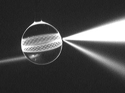
Figure 4 A spherical whispering gallery mode optical resonator. This photograph was obtained by submerging the sphere and the fiber in a liquid.
Examples of OEOs with various configurations are now numerous and may be readily found in the literature.5 OEOs with fiber delay lines as the energy storage elements that produce signals with frequencies as high as 48 GHz have been demonstrated. An X-Band OEO with spectral purity of –163 dBc/Hz at 10 kHz has also been demonstrated.6 These architectures generally employ several km of optical fiber, which results in rack mountable units. A high performance compact OEO about the size of a computer mouse pad has also been developed.7
Aside from their size, fiber based OEOs are also unsuitable for certain applications where the noise spectrum must be absolutely smooth. This is because OEO is inherently a multi-mode oscillator, with the filter selecting the oscillating mode. Modes other than the one selected by the filter, present due to the length of the loop (in which the fiber is the longest element), are suppressed; unless the loop is so long as to produce modes with frequency separation smaller than the filter bandwidth. In this case the surviving modes, although much diminished by the filter, appear as noise peaks in the oscillator phase noise spectrum. Since narrowband electronic filters at X-Band and higher frequencies are difficult to realize, high performance OEOs exhibit noise peaks in the spectrum starting at a frequency corresponding to the length of the fiber, and at harmonics of this frequency, with diminishing amplitude based on the filter shape.
One approach for avoiding this problem is the use of an optical resonator in place of the fiber. High-Q optical resonators such as Fabry-Perot cavities are readily available, and can serve both as the filter and the storage element. This approach has been employed with COEO to successfully reduce the phase noise due to the so called “super mode” noise peaks.8 The COEO architecture already reduces the noise peaks due to the smaller length of fiber, and thus wider frequency interval between the modes of the oscillator to make filtering of the unwanted modes more effective. The use of the Fabry-Perot cavity aids this approach to further clean up the spectral density of the phase noise. Despite this gain, implementation of the Fabry-Perot cavity in the loop leads to additional complexity, and more sensitivity to environmental disturbances such as temperature variations and vibration.
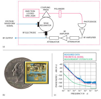
Figure 5 Schematic diagram of a microresonator-based OEO (a) and photo of the packaged component (b). The oscillator produces the performance shown in (c) at 12 GHz.
Whispering Gallery Mode Oscillator
Recently, a new type of miniature optical resonator has been employed for use in the OEO. Known as whispering gallery mode (WGM) resonators, these are structures made with a transparent material and are geometrically axio-symmetric, ranging in size from a few mm to a few tens of microns in diameter (see Figure 4).9 This resonator is made out of glass by heating the tip of an optical fiber. Light is coupled in with a fiber faintly visible on the left. Excited modes are visible as a band of light that forms close to the surface of the sphere at the equator. The name whispering gallery mode was coined by Lord Rayleigh to describe special acoustic modes supported by high (acoustic) Q structures such as the dome of St. Peter’s cathedral in London. The optical counterparts are modes that propagate close to the surface of the resonator and display extremely high quality factors, so that light may be trapped in them for 100 micro-seconds or longer. The narrow bandwidth associated with high Q in WGMs can be used as an optical filter in the OEO loop. More importantly, WGM resonators made of electro-optic material such as lithium niobate can be used to serve both as the high Q element in the OEO loop, and as the modulator function. Since whispering gallery modes extend outside the resonator with an evanescent tail, light can be coupled in and out of the resonator with any structure that produces an evanescent field, such as a prism or a fiber taper. Oscillators of this type have recently been introduced in a miniature package the size of a postage stamp, producing spectrally pure signals at X- and Ka-Bands (see Figure 5).10
The advent of femto second (fs) mode lock lasers has provided a new approach for generation of spectrally pure RF signals. These lasers consist of an optical material with Kerr nonlinearity placed in an optical cavity to produce a train of short pulses that in frequency domain represent an optical frequency comb (see Figure 6).11 The harmonics of this optical comb are coherent, and can mix on a photodetector to produce an RF signal at the output. Optical frequency combs produced by fs mode lock lasers can span an octave, a property that allows stabilizing them by comparing the frequency of a comb tine multiplied by 2 with its second harmonic, to lock the frequency interval of the comb. This scheme results in realization of a true frequency divider to relate the optical frequency to the comb repetition rate. As with any divider, the fs comb divides the noise of the laser by the ratio of the laser frequency to the RF repetition rate. So by locking the laser to a high finesse optical cavity and narrowing its linewidth, the output of the photodiode on which the comb harmonics mix can result in an exceptionally low noise RF signal. Such a scheme has produced the lowest noise for close to carrier frequencies at 10 GHz.12 Despite their great promise, fs mode lock lasers are relatively large in size, as compared to electronic oscillators, and are susceptible to environmental perturbations. They also are limited in frequency to RF and X-Band.
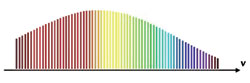
Figure 6 An optical frequency comb can be generated with a fs pulsed mode lock laser.
Recently, a new generation of optical frequency comb has been demonstrated with the WGM resonator. One of the consequences of the extremely high Q of WGM resonators is that a small amount of input power can generate a large power density in the mode. Thus a few milliwatts of light can build up to MW levels in the tiny volume of a high Q mode. Such large power densities excite nonlinearities, such as Brillioun, Raman, and parametric effects, depending on the characteristics of the resonator host material. In material with cubic nonlinearity, four-wave mixing can be excited. In this process, two photons from a light field exciting a given mode can be transferred to two photons each in a mode on either side of the excited mode.13 If the field in the originally excited mode is strong enough, the fields in adjacent modes will grow to a point where their own adjacent modes are excited. This cascaded parametric process can produce a comb of frequencies separated by the FSR of the modes in the resonator (see Figure 7).14
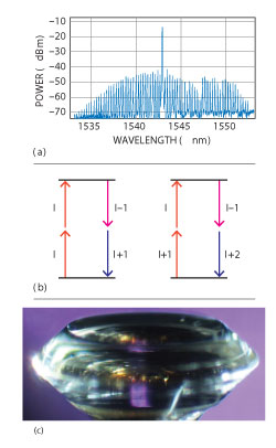
Figure 7 An optical frequency comb (a) produced via four-wave mixing process (b) with a magnesium fluoride resonator (c).
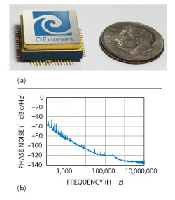
Figure 8 Packaged Kerr comb oscillator (a) and its phase noise at Ka-Band (b).
Certain parameters such as the frequency of the laser and geometry of the resonator may be adjusted to a point where all tines of the comb are coherent with respect to each other, and can beat to produce a highly spectrally pure signal. Since crystalline WGM optical micro-resonators can be readily fabricated with an FSR in X-Band or at higher frequencies, the approach promises a new generation of small, low power, and highly spectrally pure microwave and mm-wave sources.15 Such an all-optical oscillator has been produced at OEwaves in a tiny package the size of a postage stamp (see Figure 8).16 A feature of this oscillator, related to its tiny size, is its extremely low acceleration sensitivity, smaller than 10-11/g for a bare, uncompensated device. This low level of acceleration sensitivity is unprecedented in any type of uncompensated oscillator previously demonstrated.
Finally, mechanical resonances of WGM resonators can also be excited with light, when properly designed.17 These opto-mechanical resonances are in the MHz range, and are rather weak, so they do not readily compete with high performance quartz oscillator. Nevertheless, they provide an optical means for RF generation that may find use in future integrated photonics circuits. The study of Kerr combs produced by WGM resonators is by no means complete, and researchers continue to shed light on many aspects of it, particularly as pertains to production of spectrally pure microwave and mm-wave signals.
Conclusion
The subject of optical generation of microwave and mm-wave reference signals is fairly new. However, the technology is evolving rapidly, and already presents a new and compelling approach for improving the performance of advanced data, communications, radar and other systems that require high performance oscillators with small size, weight and power, at frequencies in the range of 10 to 300 GHz. This exciting field is still growing and is poised to radically change the way we think of the generation of high performance signals for electronic applications.
References
1. J.R. Vig, “Quartz Crystal Resonators and Oscillators for Frequency Control and Timing Applications – A Tutorial,” www.ieee-uffc.org/frequency-control/tutorials.asp.
2. X.S. Yao and L. Maleki, “Optoelectronic Oscillator for Photonic Systems,” IEEE Journal of Quantum Electronics, Vol. 32, No. 7, July 1996, pp. 1141-1149.
3. D. Eliyahu and L. Maleki, “Tunable, Ultra-Low Phase Noise YIG based Opto-Electronic Oscillator,” IEEE MTT-S International Microwave Symposium Digest, Vol. 3, June 2003, pp. 2185-2187.
4. S. Fedderwitz, A. Stoehr, S. Babiel, V. Rymanov and D. Jager, “Optoelectronic Band Oscillator With Gigahertz Tuning Range and Low Phase Noise,” IEEE Photonics Technology Letters, Vol. 22, No. 20, October 2010, pp. 1497-1499.
5. X.S. Yao, L. Davis and L. Maleki, “Coupled Optoelectronic Oscillators for Generating Both RF Signal and Optical Pulses,” Journal of Lightwave Technology, Vol. 18, No. 1, January 2000, pp. 73-78.
6. P. Devgan, “A Review of Optoelectronic Oscillators for High Speed Signal Processing Applications,” ISRN Electronics, Vol. 2013, Article ID 401969, 2013, 16 pages.
7. D. Eliyahu, D. Seidel and L. Maleki, “Phase Noise of a High Performance OEO and an Ultra Low Noise Floor Cross-Correlation Microwave Photonic Homodyne System,” IEEE International Frequency Control Symposium Proceedings, May 2008, pp. 811-814.
8. D. Eliyahu and L. Maleki, “Modulation Response (S21) of the Coupled Opto-electronic Oscillator”, IEEE International Frequency Control Symposium Proceedings, August 2005, pp. 850-856.
9. J.M. Kim and D. Cho, “Optoelectronic Oscillator Stabilized to an Intra-Loop Fabry-Perot Cavity by a Dual Servo System,” Optics Express, Vol. 18, No. 14, July 2010, pp. 14905-14912.
10. A.B. Matsko and V.S. Ilchenko, “Optical Resonators With Whispering-Gallery Modes-Part I: Basics,” IEEE Selected Topics in Quantum Electronics, Vol. 12, No. 1, January-February 2006, pp. 3-14.
11. L. Maleki, V.S. Ilchenko, A.A. Savchenkov and A.B. Matsko, Practical Applications of Microresonators in Optics and Photonics, CRC Press, Boca Raton, FL, 2009, pp. 133-210.
12. L. Maleki, “Sources: The Optoelectronic Oscillator,” Nature Photonics Technology Focus, Vol. 5, No. 12, December 2011, pp. 728-730.
13. K. Volyanskiy, P. Salzenstein, H. Tavernier, M. Pogurmirskiy, Y.K. Chembo and L. Larger, “Compact Optoelectronic Microwave Oscillators Using Ultra-High Q Whispering Gallery Mode Disk-Resonators and Phase Modulation,’’ Optics Express, Vol. 18, No. 21, October 2010, pp. 22358-22363.
14. T. Udem, R. Holzwarth and T.W. Hansch, “Optical Frequency Metrology,” Nature, Vol. 416, No. 6877, March 2002, pp. 233-237.
15. F. Quinlan, T.M. Fortier, M.S. Kirchner, J.A. Taylor, M.J. Thorpe, N. Lemke, A.D. Ludlow, Y. Jiang, C.W. Oates and S.A. Diddams, “Ultralow Phase Noise Microwave Generation With an Er:Fiber-Based Optical Frequency Divider,” Optics Letters, Vol. 36, No. 13, August 2011, pp. 3260-3262.
16. A.B. Matsko, A.A. Savchenkov, D. Strekalov, V.S. Ilchenko and L. Maleki, “Optical Hyperparametric Oscillations in a Whispering Gallery Mode Resonator: Threshold and Phase Diffusion,” Physical ReviewA, Vol. 71, No. 3, 2005, p. 33804.
17. P. Del’Haye, A. Schliesser, O. Arcizet, T. Wilken, R. Holzwarth and T.J. Kippenberg, “Optical Frequency Comb Generation From a Monolithic Microresonator,” Nature, Vol. 450, No. 7173, December 2007, pp. 1214-1217