
A compact tri-band bandpass filter (BPF) using three shorted stub-loaded dual-mode resonators (SSLDMR) is presented. The center frequency and bandwidth of all three passbands can be flexibly controlled by tuning the electrical length of the corresponding resonators and shorteed stubs, respectively. Moreover, each passband can be independently adjusted without affecting the other two. A prototype of a tri-band BPF centered at 2.4, 3.5 and 5.2 GHz has been designed and fabricated with six transmission zeros. Good agreement can be found between measured and simulated results.
Modern wireless communication systems such as GSM (0.9/1.8 GHz), W-CDMA (2.1 GHz), WiMAX (3.5 GHz) and WLAN (2.4/5.2 GHz) are widely used in people’s daily lives. High performance multiband bandpass filters (BPF) have become indispensable in the RF front ends of communication systems designed to work across all of these bands. To address this need, a variety of multiband bandpass filters designs have been recently proposed. Stepped-impedance resonators (SIR) are utilized to construct the dual-band and tri-band BPFs.1-3 A two-section SIR can achieve a dual-band response by tuning its geometric parameters,2 and determining the resonant frequencies of a tri-band filter is straightforward.3 It is difficult, however to control the passbands independently, and these structures are relatively complicated. Stub-loaded resonators (SLR), which can be analyzed by the odd and even-mode method, are widely used structures in the design of dual-band4-7 and tri-band filters.8,9 An open stub-loaded resonator (OSLR) has been presented and analyzed and a dual-band BPF was designed.4 A shorted stub-loaded resonator (SSLR) had been analyzed7 and a tri-band filter using both shorted and open stub loaded resonators has also been presented.9
The OSLR and SSLR have been analyzed by odd- and even-mode methods.4,5 Both the OSLR and SSLR have demonstrated that the fundamental even-mode resonant frequency can be shifted by changing the stub length, whereas the fundamental odd-mode resonant frequency is preserved. The odd-mode and even-mode resonant frequencies, however, are used in two different passbands. Thus the bandwidths of the passbands mainly depend on the coupling coefficients, which can only be adjusted over a relatively narrow range.
In this article, the odd and even-modes of the SSLR are used to generate only one passband as long as the fundamental even-mode resonant frequency is close to the fundamental odd-mode resonant frequency. We call this the short-circuited stub-loaded dual-mode resonator (SSLDMR). Thus the bandwidth is determined primarily by the distance between the fundamental even-mode resonant frequency and the fundamental odd-mode resonant frequency. Our analysis shows that the bandwidth of the passband can be controlled by changing the shorted stub length. We propose a compact tri-band BPF using three different sizes of half-wavelength SSLDMRs that can have independently controllable bandwidth for each of three passbands by properly selecting the length of the shorted stubs. A tri-band BPF for WiMAX (3.5 GHz), and WLAN (2.4/5.2 GHz) applications was fabricated and measured.
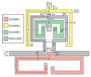
Figure 1 Schematic diagram of the proposed tri-band BPF.
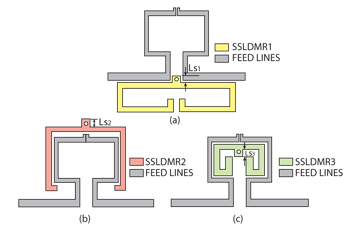
Figure 2 Structures of three single-band filters with only SSLDMR1 (a), SSLDMR2 (b) and SSLDMR3 (c).
Filter Design
The structure of the proposed compact tri-band BPF is shown in Figure 1. It consists of a pair of meandering feed lines and three sets of folded half-wavelength SSLDMRs with frequencies at 2.4, 3.5 and 5.2 GHz. A pair of vertical parallel coupling lines at the end of each feed line is used for increasing source-load coupling. This structure enables each passband to be independently designed since there is no mutual coupling among the three sets of SSLDMRs.
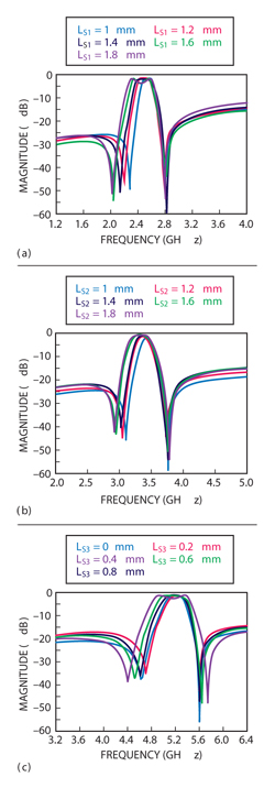
Figure 3 Frequency response versus stub length for the filters in Figure 2 - LS1 (a), LS2 (b) and LS3 (c).
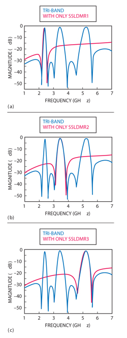
Figure 4 Tri-band/single-band simulation results of the proposed filter. With three SSLDMRs/with only SSLDMR1(a), with three SSLDMRs/with only SSLDMR2 (b), and with three SSLDMRs/with only SSLDMR3 (c), (dimensions of the structure are the same).
To verify the approach, three single-band filters with only one folded SSLDMR and the same pair of meandering feed lines are each simulated by using the Ansoft HFSS simulator. All the other dimensions are fixed except the stub lengths (LS1, LS2 and LS3) shown in Figure 2. From Figure 3, we can conclude that the bandwidth of each passband can be adjusted over a wide range by changing the shorted stub lengths (LS1, LS2, LS3) respectively.
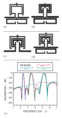
Figure 5 Topology of three dual-band filters and a combined tri-band filter – dual-band filter using 1st and 2nd passbands (a), dual-band filter using 1st and 3rd passbands (b), dual-band filter using 2nd and 3rd passbands (c), tri-band filter (d); simulated frequency responses of the four filters (e).
Shown in Figure 4 are the simulated results of the single-band and tri-band filters. It demonstrates that any single passband can be independently designed and adjusted while the other two are not affected. The proposed filter achieves tri-band performance using three parallel transmission paths for the three individual passbands. The feed design provides sufficient isolation for the three specific passbands, and the bandwidth of each passband can be adjusted independently by changing the shorted stub length of the corresponding SSLDMR without affecting the other two passbands. Also verified are the responses of four filters with the same feed line structure, i.e., three dual-band filters using any two SSLDMRs and a combined tri-band filter using three SSLDMRs (see Figure 5).
Since the coupling paths of the three passbands are isolated, the center frequency and bandwidth of all three passbands are independently controlled by adjusting the electrical length of each resonator and each shorted stub, respectively. Source-load coupling is utilized to improve selectivity with six transmission zeros on either sides of all three passbands; therefore, any single-band, dual-band, or tri-band microstrip BPF with good frequency selectivity can be designed using the proposed structure by changing the number and position of the SSLDMRs. To obtain a more compact structure, three sets of SSLDMRs are folded and are located in close proximity to the pair of meandering feed lines.
Experimental Results
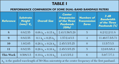
The prototype tri-band BPF with center frequencies at 2.4, 3.5, 5.2 GHz was fabricated on an RF-35 substrate with a relative dielectric constant of 3.5 and a thickness of 0.508 mm. The dimensions (units: mm) of the filter are: L1 = 17.9, L2 = 13.2, L3 = 9.5, LS1 = 1, LS2 = 0.8, LS3 = 0, Lf = 13.9, W = 1.1, WS1 = WS2 = WS3 = 1, W1 = 0.7, W2 = Wf = 0.6, W3 = 0.8, W4 = 0.2, W5 = 0.45, g1 = 0.3, g2 = 0.35, g3 = 0.65, g4 = 0.18, G1 = 1.5, G2 = 0.1. Via diameters are all 0.5 mm. The distances between the centers of each via and the end of each stub are all 0.4 mm. The stub lengths of SSLDMR1, SSLDMR2 and SSLDMR3 are 1, 0.8 and 0 mm, respectively. A comparison of the simulated and measured frequency responses is shown in Figure 6. The measured results are in good agreement with the full-wave simulation. Slight deviations are attributed to fabrication error. The measured 3 dB bandwidths for the three passbands (2.4, 3.5 and 5.2 GHz) are 5.0, 7.7 and 7.3 percent, respectively. Minimum insertion losses, including the losses from two SMA connectors, are 1.78, 1.63 and 1.72 dB, respectively. Six transmission zeros on either side of three passbands are located at 2.17, 2.62, 3.04, 3.94, 4.55 and 5.65 GHz. Its size is only 14.9 × 15 mm including the feed lines (see Figure 7). Table 1 summarizes some previously reported performance of tri-band bandpass filters for comparison, demonstrating that this work features reduced size and improved selectivity.
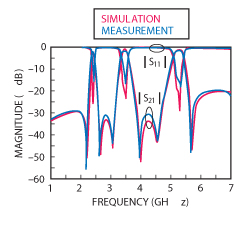
Figure 6 Simulated and measured results of the prototype tri-band BPF.
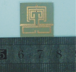
Figure 7 Photograph of the fabricated tri-band BPF.
Conclusion
This article presents a tri-band BPF with three different sizes of SSLDMRs. The bandwidths of the three passbands can be all independently controlled. It has high isolation in a compact size. The design procedure is simple and it can be easily and inexpensively fabricated using common printed circuit board technology. Moreover, any single-band, dual-band, or tri-band microstrip BPF with good frequency selectivity can be designed using this structure.
Acknowledgment
This work was supported by the China Scholarship Council (CSC).
References
- 1. C.F. Chen, T.Y. Huang and R.B. Wu, “Design of Dual- and Triple-Passband Filters Using Alternately Cascaded Multiband Resonators,” IEEE Transactions on Microwave Theory and Techniques, Vol. 54, Issue 9, September 2006, pp. 3550-3558.
- 2. M.H. Weng, H.W. Wu and Y.K. Su, “Compact and Low Loss Dual-Band Bandpass Filter Using Pseudo-Interdigital Stepped Impedance Resonators for WLANs,” IEEE Microwave and Wireless Components Letters, Vol. 17, Issue 3, March 2007, pp. 187-189.
- 3. C.I.G. Hsu, C.H. Lee and Y.H. Hsieh, “Tri-Band Bandpass Filter With Sharp Passband Skirts Designed Using Tri-Section SIRs,” IEEE Microwave and Wireless Components Letters, Vol. 18, Issue 1, January 2008, pp. 19-21.
- 4. X.Y. Zhang, J.X. Chen, Q. Xue and S.M. Li, “Dual-Band Bandpass Filters Using Stub-Loaded Resonators,” IEEE Microwave and Wireless Components Letters, Vol. 17, Issue 8, August 2007, pp. 583-585.
- 5. Y.C. Li, H. Wong and Q. Xue, “Dual-Mode Dual-Band Bandpass Filter Based on a Stub-Loaded Patch Resonator,” IEEE Microwave and Wireless Components Letters, Vol. 21, Issue 10, October 2011, pp. 525-527.
- 6. X.Y. Zhang, C.H. Chan, Q. Xue and B.J. Hu, “Dual-Band Bandpass Filter With Controllable Bandwidths Using Two Coupling Paths,” IEEEMicrowave and Wireless Components Letters, Vol. 20, Issue 11, November 2010, pp. 616-618.
- 7. F.C. Chen, Q.X. Chu and Z.H. Tu, “Design of Compact Dual-Band Bandpass Filter Using Short Stub Loaded Resonator,” Microwave and Optical Technology Letters, Vol. 51, Issue 4, April 2009, pp. 959-963.
- 8. Q.X. Chu, X.H. Wu and F.C. Chen, “Novel Compact Tri-Band Bandpass Filter With Controllable Bandwidths,” IEEE Microwave and Wireless Components Letters, Vol. 21, Issue 12, December 2011, pp. 655-657.
- 9. F.C. Chen, Q.X. Chu and Z.H. Tu, “Tri-Band Bandpass Filter Using Stub Loaded Resonators,” Electronics Letters, Vol. 44, Issue 12, June 2008, pp. 747-749.
- 10. X. Lai, C.H. Liang, H. Di and B. Wu, “Design of Tri-Band Filter Based on Stub Loaded Resonator and DGS Resonator,” IEEE Microwave and Wireless Components Letters, Vol. 20, Issue 5, May 2010, pp. 265-267.
- 11. F.C. Chen, Q.X. Chu, and Z.H. Tu, “Design of Compact Dual- and Tri-band Bandpass Filters Using l/4 and l/2 Resonators,” Microwave and Optical Technology Letters, Vol. 51, Issue 3, March 2009, pp. 638-641.