
Whether for enterprise, commercial, government or maritime services, customers who operate in remote and harsh environments use satellite services for time-sensitive, mission critical communications. Whether communicating back to headquarter offices or providing morale services to staff and crew members, it is vital that these customers that operate in remote and harsh landscapes have access to high availability, reliable communications links.
High throughput satellite (HTS) technologies with unprecedented bandwidth and power resources are being viewed as “the wave of the future” for satellite communications and networking services. Despite this tremendous potential, there is a great deal of misperception and lack of understanding about these new technologies among both customers and the industry at large. With different options, how do you pick the best one for your company’s needs?
While Ka-Band satellite services have gained traction and general customer acceptance and are often viewed as the “shiny penny” of satellite communications, traditional Ku-Band SATCOM is generally viewed like business-as-usual and does not necessarily excite the imaginations of very small aperture terminal (VSAT) customers. This perception has been in part created by industry hype over Ka-Band, but this observation is overstated and does not fit all application environments. A similar phenomena was observed in the 1980s when Ku-Band systems first appeared. Many industry pundits speculated that C-Band would all but disappear from use in VSAT applications. It has turned out to be quite the contrary, as C-Band continues to grow as an important band in industrial, military and especially maritime applications where atmospheric attenuation is particularly acute. In general, all frequency bands have their place in satellite communications.
In order to better understand the real potential and practical application of this new generation of HTS spacecraft, Harris CapRock conducted an in-depth engineering analysis of several HTS systems for customers operating in remote, mission-critical environments. Harris CapRock used industry data combined with its team’s experience to compile an analysis that enables a clearer view of HTS capabilities considering beam coverage, power consumption, frequency band, link availability and actual cost per bit of transponded capacity.

Figure 1 High throughput satellite spot beams.
A Closer Look into High Throughput Satellites
A HTS system is defined as a satellite system that uses a large number of small spot beams distributed over a particular service area (see Figure 1). These spot beams provide high signal strength and signal gain (EIRP and G/T), which allow the satellite to close links to small aperture earth stations at high data rates with positive rain-fade margin to provide good overall link availability. A typical HTS has a significant number of ultra-wideband transponders distributed among the beams, each with a bandwidth of more than 100 MHz.
HTS solutions include both Ka-Band and Ku-Band platforms. Each band is not interchangeable, and has its own strengths and weaknesses which make each better suited for some applications and less suited for others. To help understand the differences between HTS Ka-Band and HTS Ku-Band, it is best to know some information about HTS systems in general:
- Coverage area is divided into many small spot beams, unlike one large beam from a conventional satellite
- Each spot beam covers an area 1 to 2 percent the size of a diffused conventional beam
- Spot beams support large-scale frequency reuse for high data rates
- Smaller, more concentrated spots support higher performance than one conventional beam
- HTS systems operate in either Ku- or Ka-Band frequency.
HTS systems combine the exceptional spectrum efficiency and performance of spot-beam antennas with ultra-wideband transponders to enable unprecedented levels of bandwidth and throughput. Each spot beam reuses frequencies in multiple carriers so that a single HTS spacecraft can provide five to 10 times the capacity of traditional satellites. For the customer, this provides the potential to dramatically increase data rates, upwards of 100 Mbps to a single site and improve application performance compared to traditional satellite-based communications.
HTS spot beams generally have 3 dB beamwidths between 0.5 and 1.5 degrees. Spacecraft have been built or proposed with antennas ranging from a dozen to more than 100 spot beams. HTS payloads commonly have 5 to 10 GHz of transponder bandwidth, but channel frequencies are reused numerous times in geographically isolated spots so that the spectrum needs of the system are constrained within available satellite bands. Spot beams may be steered or fixed relative to the satellite. Since the spot beams have limited geographic coverage, HTS systems generally have special gateway beams and transponders specifically to support connections with teleports.
The narrow beamwidths associated with spot beam antennas are created by employing relatively large antenna structures that focus downlink energy and have large areas for collecting uplink energy. Consequently, these antennas greatly improve link performance, providing high data rates at much better availability than traditional regional and hemispherical beams. However, since these antennas accomplish their link improvements by focusing the radio signals into small spots on the earth’s surface, these improvements come at the price of geographic coverage.
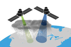
Figure 2 Ka-Band HTS coverage vs. throughput trade off.
Because the coverage and performance trade off is particularly important for Ka-Band HTS systems, where the links are especially susceptible to propagation impairments due to rain and other atmospheric disturbances, the developers of HTS systems must balance their geographic coverage needs against the link performance that small spot beams can provide (see Figure 2). Antenna size scales inversely with the square of the frequency. Therefore, using very narrow spot beams to mitigate these propagation impairments is particularly attractive in Ka-Band. On the other hand, the number of transponders, the payload complexity and the spacecraft power requirements all scale directly with the number of beams on the satellite, so very small beams also limit the available service area of the HTS.
The natural contention between coverage and link performance has tended to divide Ka-Band HTS systems into two classes: those optimized primarily to achieve high availability links and those optimized primarily for large area coverage. The first class is characterized by fractional-degree antenna beamwidths, whereas the second class sacrifices link performance to use larger spot beams. Of course, a great many considerations and trade-offs go into the development of satellite communications systems, so this classification is a simplification of a much more complex situation.
Ka- vs Ku-Band: Pondering Performance
When examining the advantages and disadvantages of Ka-Band from a technical standpoint, it is important to view the pros and cons in terms of specific target markets. In remote, harsh environments, customers generally place a higher priority on network reliability, user throughput and application performance. On one side, there are those that want a remote workspace configured as a VPN with guaranteed bandwidth and a solid, reliable service that is capable of running sophisticated applications in a heavy duty commercial environment. Alternatively, there are casual users who do not necessarily need access to a complete network, but to simply provide their crew members with access to the Internet and voice communications. Side-by-side technical and cost comparisons of Ka- and Ku-Band HTS solutions show advantages and disadvantages for both system solutions.
Cost
The use of spot beams allows both the Ku- and Ka-Band systems to achieve high spectrum efficiencies. Further, HTS systems in both bands use ultrawideband transponders and frequency reuse. These features create an economy of scale that allows satellite operators to offer bandwidth at attractive and comparable prices. However, this advantage is eroded when a Ka-Band system sacrifices link performance in favor of coverage by using larger spot beams. These factors are not discriminators between the Ku-Band spot and Ka-Band small spot systems, but Ka-Band large spot systems do not fare as well from this perspective. As a result, HTS Ku-Band spot systems actually tend to demonstrate a cost per bits per second that is more favorable than Ka-Band, when compared at the same link availability, design requirement and larger spot beam sizes.
Coverage
Spot beam systems are, by their nature, limited in coverage. Each spot beam generally covers at most a few thousand square kilometers. However, some HTS systems provide large fields of spot beams that collectively create continental and even global coverage, whereas others offer only a relatively small number of fixed or steerable spots in targeted areas. Ku- and Ka-Band large spot beams are similar in beamwidth and so are generally comparable in system coverage. Ka-Band small spot beams, however, generally cover only about 10 or 15 percent of the area covered by a large spot beam and these spacecraft tend to offer less total spot beam coverage.

Figure 3 Intelsat Epic satellite platform uses multiple bands and beam sizes.
Flexibility and Bandwidth Portability
Commitment to the development of an HTS system represents a substantial and long-term investment of resources, not just for the satellite operator but also for network providers and customers as well. The anticipated lifetime of these systems is greater than a decade, and yet their target marketplace is dynamic. Over the long term, the energy, maritime and government sectors are subject to transformation or disruption by factors such as new mineralogical discoveries, changes in shipping patterns or international crises. Thus it is advantageous to be able to relocate services and capacity to respond to major changes in the marketplace. Multiple satellite systems with near global coverage such as some of the Ku- and Ka-Band large spot systems can respond to these changes more readily than the small spot Ka-Band HTS systems (see Figure 3). Ku-Band HTS systems and Ka-Band systems with other frequency backup have the additional benefit that their VSAT links can, if necessary, be reallocated to traditional systems, albeit in some cases at a loss of service performance if the back-up service operates in a significantly longer wavelength.
Recovering from Satellite Failure
A great deal of Ku-Band satellite service provided by traditional spacecraft is available virtually everywhere in the world. Because many Ka-Based systems are offered on closed networks, the services are often scarce. Thus, in the event of a failure on an HTS spacecraft resulting in loss of service to a spot beam or beams, it is possible to mitigate the service impact by migrating customers in the affected area to an alternate Ku-Band satellite. This same back up capability is less likely to be available at Ka-Band. Unless the customer adds a standby service for Ka-Band in Ku-Band or some other satellite band which would require additional ground terminal hardware and on-site electronics, their backup capabilities will be limited.
VSAT and Equipment Costs
Ka-Band VSAT systems are less common in the marketplace and therefore can be more expensive than Ku-Band systems of similar performance. While “mass market” systems designed primarily for direct-to-home users are becoming more available at low price points, these systems are generally not suitable for industrial environments in terms of both performance and hardware reliability. The realities of RF propagation drive performance requirements for larger Ka-Band earth terminals. This means that sub-meter sized consumer grade terminals cannot deliver the speed or link availability typically required by industrial installations. Larger Ka-Based terminals of 1.2 m or greater are not yet produced in meaningful quantities and therefore remain more expensive than Ku-Band terminals. The bottom line is that the costs of HTS Ka-Band equipment may decrease as sales volumes increase, but the current costs of major components and systems are significantly higher than HTS Ku-Band equipment.
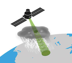
Figure 4 Adaptive coding can reduce the effects of rainfall attenuation.
Service Reliability
The much smaller wavelength and higher frequency of Ka-Band makes its links far more susceptible to disruption from weather and other atmospheric disturbances than Ku-Band links. The use of spot beams improves Ka-Band performance, but links with Ku-Band spot beams remain much more reliable. Obtaining the same level of link availability and data rate (say more than 99.5 percent) in a Ka-Band spot beam would require exponentially more transponder power than a comparable link and antenna size in Ku-Band. It is therefore much more difficult and expensive to provide high availability and reliable services in Ka-Band than in Ku-Band – particularly in regions where heavy rainfall is common (see Figure 4).
Ka-Band radio signals are more severely impacted by rain and other transient propagation conditions than lower frequency signals like Ku-Band. Consequently, Ka-Band links require higher fade margins for a given service availability than lower frequency links, and Ka-Band HTS spacecraft are designed to provide these margins. As noted, this can result in a cost penalty for the Ka-Band systems when customers demand high service reliability. However, this disadvantage can in some cases be turned to the advantage of Ka-Band services, for customers whose service needs can tolerate lower availability – such as mass market or consumer clients.
HTS Space Systems Design Concerns
Originally, most HTS systems were designed for mass markets and to operate in Ka-Band where small aperture antennas can provide narrow spot beams. However, satellite operators are now applying HTS technology and spot beam antennas to new Ku-Band spacecraft. As these HTS systems proliferate, operators of VSAT networks will have new technology choices when implementing solutions tailored to the application environment of their clients. HTS systems and capabilities can be leveraged in a variety of ways to extend the portfolio of service offerings available on the market.
Several technology options are available to HTS spacecraft developers, and each has advantages and disadvantages for any particular mission and marketplace. As always, the spacecraft design team must comprehensively trade these options in the context of the overall application requirements and target market. While most HTS payload trades follow well-established satellite design tenets, their more complex wideband electronics and large antennas may alter the relative emphasis placed on certain aspects of the trade space compared to more traditional spacecraft designs.
In spite of the many innovative advances in lowering launch system costs over the last few decades, the cost to orbit remains the largest single factor driving the selection of HTS payload and antenna technology. Size, weight and power requirements (SWaP)are often more significant cost drivers than the spacecraft components themselves. This is particularly true for global system operators that expect to deploy a number of HTS systems based on a common spacecraft design. Large, complex wideband HTS payloads are particularly taxing for spacecraft platforms from the SWaP perspective. Consequently, spacecraft designers tend to be more open to the use of deployable assemblies, exotic materials and other technologies that can reduce the weight and volume of the overall HTS.
Possibly the most vexing aspect of HTS architecture and technology selection facing the space system design team is having to determine how much flexibility should be incorporated into the payload to allow the system to respond to changes in the market. Payload switching, channelization and antenna steering capabilities determine whether a spacecraft is narrowly optimized to serve a particular market, or whether its coverage and capacity can be readily adapted to changing market needs.
There is ample evidence that a well-designed and constructed spacecraft can have a useful service life measured in decades, but there is far less evidence that space system operators (or anyone else) can accurately predict market trends over a similar time span. Incorporating a great deal of flexibility into such a costly and long-lived asset might seem an obvious choice, but flexibility inevitably sub-optimizes performance and/or capacity and adds cost to the system. Thus, payload flexibility may compromise the system’s ability to serve its immediate target market profitably in order to be ready for something that might or might not happen. Nearly all commercial HTS payloads have been designed for specific markets and applications, although some of the HTS under development are placing more emphasis on flexibility.
Since the use of a relatively large number of spot beams is a distinguishing characteristic of HTS systems, HTS antenna system design is particularly interesting and challenging. Spacecraft designers have a number of proven but competing spot beam antenna and transponder switching technologies available when developing an HTS, and their choices are driven by the needs of the marketplace and application for which the satellite is intended.
There are three fundamental spot beam antenna technologies available for HTS applications: phased arrays, multi-feed reflectors and multiple single-beam antennas. These technologies can be applied as the exclusive antenna system for an HTS or a hybrid antenna system can be used. All of these choices have been used in commercial satellite systems and each has strengths and weaknesses for a given application. It is important that the payload design team have experience in all of these options so that they can make the optimum choice for the particular system requirement.
Is HTS the Wave of the Future?
Customers with industrial-grade operations in remote and harsh locations demand highly reliable communications services and have ever increasing bandwidth requirements. For these kinds of clients, Ku-Band HTS systems may have a distinct advantage over Ka-Band HTS systems, as well as traditional regional and hemispheric beam systems. While Ka-Band HTS can be quite competitive for customer services that do not require particularly high reliability, such as consumer broadband access, they generally do not enable the bandwidth or link availability required by industrial customers, without an excessive, and therefore costly, use of spacecraft power and resources.
Both Ka- and Ku-Band frequencies show great promise to provide customers with a variety of next generation communications solutions, and we are beginning to see a real change and a wealth of new possibilities for satellite communication. In order to adapt and thrive in the face of these new possibilities, it is essential that CTOs and CIOs ensure their satellite systems can support the higher data rate communications forecast in the coming years.
As Ka- and Ku-Band HTS systems come online, operators such as Harris CapRock will expand their multi-band services to intelligently deploy systems that strike an optimal balance of speed, availability and cost. However, SATCOM spectrum remains limited and a valuable resource. Service providers and operators must determine how best to fit the capabilities and limitations of this new technology into their service portfolio to best meet the needs of their customers.
This article’s subject matter and the HTS spacecraft analyzed by the authors are in geosynchronous earth orbit. There have been promising proposals for Ka-Band HTS systems in low earth orbit and medium earth orbit as well. Harris CapRock is following these developments with interest. However, this article does not address systems outside the geosynchronous arc.