
Spectral proximity of 4G communication signals to S-Band radar frequencies can result in the introduction of false target signals into a radar sensor system. Furthermore, the magnitude of 4G communication signal levels (when radiated in the vicinity of a radar) can cause the radar receiver to begin to limit then fully activate the receiver protector, and so cause any synchronous target signal to be lost.
An updated pre-TR limiter receiver protector (RxP) has been designed to tolerate high levels of 4G signal interference, and enables the use of a low-power filter at the RxP output to minimize 4G signals before they enter the radar receiver. This approach has preserved the operational performance characteristics of the legacy pre-TR limiter design, and presents a robust alternative to high-power filtering at the radar antenna.
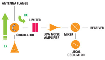
Figure 1 Surveillance radar transceiver functional schematic.
Allocation of communication frequency bands close to existing radar frequencies1-3 has seen study of potential interference and disruption effects in surveillance radar systems.4-7 As the margins between allocated frequency bands narrow, there is a growing demand for precision in the requirements for band-edge filtering of transmitted signals and out-of-band rejection of any extraneous received signal frequencies1-7 which otherwise threaten the mission reliability of the radar system.
4G interference signals can reach and activate the limiter causing it to compress and attenuate all in-band incoming signals (including target echo returns), as illustrated in the radar system schematic shown in Figure 1. These 4G signals can also pass through the RxP and generate false signal returns or saturate the receiver.
IF Filtering of 4G Signals
Radar receivers generally incorporate filtering within the IF stages; however, it may not be practical to reduce the impact of 4G interference by introducing narrowband filtering at this point because the desired signal and all interfering signals must pass through the receiver protector into the low-noise microwave amplifier (LNA) and frequency converting mixer before reaching the IF amplifier.
Consequently this “downstream” IF filtering approach can lead to:
- Limiter compression and impeded target signal reception due to the attenuation from the receiver protector
- Harmonic generation from the 4G signal; saturation and potential damage of the LNA
- In- (radar) band products of the mixing process; third-order intermodulation can generate products at frequencies up to 2.81 GHz from base station signals in the 2.6 GHz 4G communications band
- Saturation of the IF amplifier leading to missed and erroneous target returns.
RF Input Filtering of 4G Signals
The solution of filtering the received signal before the receiver protector and gain stages8,9 relies on a filter capable of handling the high-level antenna reflection signals and potential high-power fault conditions and having a sufficient number of high-Q elements to attenuate the 4G signals.
With this “up-stream” approach, incoming RF power levels could exceed the filter’s electric field rating and cause internal arcing, leading to long-term filter degradation – this is especially a problem when the system is specified to operate at high altitude without waveguide pressurization.
Alternatively, a power-compliant filter design can prove excessively large in size, leading to accommodation issues with a retro-fit filter installation.
Modification of the Receiver Protector
Receiver LNAs have been optimized to operate in radar receivers close to 4G communication signal bands.10 It is also feasible to enhance the behavior and operation of the duplexer and receiver protector to mitigate any signal interference, and avoid further modification of the receiver LNA.
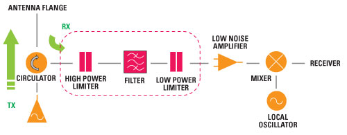
Figure 2 Functional concept for a 4G-resilient surveillance radar transceiver.
An updated receiver protector design is presented for S-Band (2.8 GHz) applications, which accommodates a higher input compression level to mitigate attenuation in the radar receive chain from the ingress of 4G signals. This updated RxP was designed for use with a low-power filter and secondary low-power limiter (included in front of the receiver LNA) to allow reliable filtering of 4G interference signals and maintain robust protection of the LNA as shown in Figure 2.
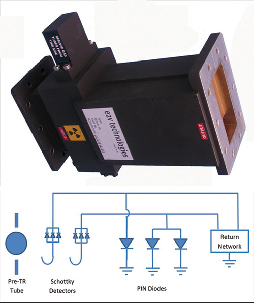
Figure 3 General arrangement of a legacy S-Band pre-TR limiter receiver protector.
4G signals within the frequency bands 2.5 to 2.69 and 3.4 to 3.6 GHz, at +23 dBm peak power, can be incident on an S-Band radar limiter receiver protector.12 The existing pre-TR limiter design (see Figure 3) did not meet this interference specification owing to too low a compression point: the limiter was therefore re-designed to increase its compression threshold, and to replace the pre-TR gas cell filling with a non-radioactive fill.11 The limiter redesign approach was to conserve the fit, form and function of the original unit, whilst optimizing the PIN diode arrangement for higher compression operation.
Updated Receiver Protector Design
Modifications were made in the waveguide structure and PIN diode configuration of the limiter design:
- PIN diodes with a thicker I-region and reduced sensitivity that therefore require a higher level of incident RF before limiting starts
- Modification of the return DC current path, to impede the flow of the self-generated current sufficiently to raise the limiting power value
- Modification of the tuning structure to reduce the level of coupling, reducing the power present at the PIN diode for a given power level, and improving operational reliability under high-power conditions.
The present unit (in Figure 3) had a pre-TR mount located at the input to protect the limiter section diode from higher, potentially damaging levels of incident RF power (typically > few hundred watts). Routinely a non-radioactive device solution is preferred in new and upgraded radar installations.
The use of the radioactive gas (tritium, H3) within the pre-TR tube improved the pre-TR performance by enhancing the avalanche breakdown process with the onset of a high-power RF input level, assisting the formation of a plasma discharge in the gas tube. With the tritium removed, the statistical time period to activate the pre-TR tube therefore increases, and can expose the solid-state limiter section to higher incident power levels for longer periods.
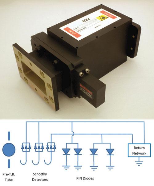
Figure 4 General arrangement of an updated S-Band pre-TR limiter receiver protector.
The updated limiter design therefore had a dual PIN diode stage incorporated into the input: this arrangement offered increased power handling capability (with minimal insertion loss increase) for robust limiter operation in conjunction with a non-radioactive pre-TR input stage. Increased power handling of the input diode stage was augmented with a more robust detector (a Schottky diode assembly lightly coupled into the input waveguide that outputs a DC bias current to the PIN diodes). This updated pre-TR limiter design is shown in Figure 4.
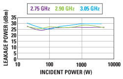
Figure 5 Flat leakage performance – updated S-Band pre-TR limiter.
Receiver Protector Performance
The specification for the updated limiter was identical to that of its legacy predecessor with the following modifications:
- Addition of the requirement for the limiter to function unimpeded by the presence of the close proximity of the new 4G signal bands
- Change to the flat and spike leakage power levels (1 and 6 W increased to 10 and 100 W, respectively).
The small-signal test results are very similar to the existing device, achieving an insertion loss better than 0.4 dB and return loss of 20 dB (VSWR approximately 1.25:1) over 2.75 to 3.05 GHz at 20°C. Similarly, the biased attenuation performance of the limiter was retained at > 60 dB over the operating frequency band.
Flat and spike leakage were measured up to a peak input power of 5 kW; the pulse rise-time of the test equipment was typically 20 ns, in line with typical transmitter system specification requirements. The flat leakage maximum was just over 1 W, and the curves shown in Figure 5 have no indication that the flat leakage level would rise rapidly at power levels beyond a 5 kW peak incident power level. At this 5 kW incident power level, the pre-TR gas tubes had fired and the level of leakage will typically remain constant for a wide range of increasing incident power levels. The spike leakage maximum measured was 48 dBm (> 60 W) and the curves shown in Figure 6 indicate that the increase in the spike leakage to be leveling-off at the 5 kW incident power level. The spike leakage pulse was typically 10 ns wide at the –3 dB point: for a 48 dBm peak leakage level this equated to a maximum spike leakage energy of ~600 nJ per pulse.
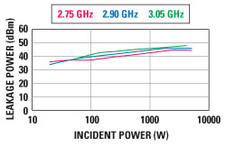
Figure 6 Spike leakage performance – updated S-Band pre-TR limiter.
The minimum power level at which the device compressed by 0.2 dB was 16.5 dBm, a 21 dB improvement over the legacy device design. Typical 4G input signal levels into a surveillance radar are dependent on a number of factors, not least being local proximity of a 4G antenna. For a close-in base station, a nominal value for 4G peak power levels incident on the receiver protector could be +13 dBm mean power, with a ~10 percent probability of peak power spikes at +10 dB above this within a 7 µs period.12
These spikes of peak power can be sufficient to cause cone breakdown in legacy TR Cell equipment, leading to high-attenuation states with significant recovery periods. The full effect of charge generation in the high-power diodes of the proposed high power limiter is under further investigation, specifically the ‘pre-energizing’ and ‘re-energizing’ effect on the solid-state limiter PIN diode stages owing to ‘pumping’ from close-range 4G interference signals where this may slow the rate of RxP recovery.
The updated, non-radioactive pre-TR gas tube breakdown level demonstrated no change in the breakdown threshold with the legacy (radioactive content) pre-TR tubes. Gas tube breakdown (with the maximum RF pulse width) was between 200 and 400 W: the variation with frequency was due to the position of RF standing wave maxima in relation to the pre-TR tube mount iris. Monitoring the leakage pulse behind the receiver protector unit showed no signs of instability pulse-to-pulse: constant recovery time values and steady leakage pulse amplitudes were consistently measured with no detectable jitter. Comparison between breakdown activations with a 40 and 1 µs pulse-width gave the expected approximate doubling of the peak power level required to initiate breakdown; nominally the breakdown power at 1 µs being twice the value at 40 µs.
Filtering and Limiting at LNA Input
Existing receiver filter and input protection on the LNA can be used in conjunction with the updated receiver protector. The updated RxP clearly has an elevated compression threshold, requiring the LNA input protection to work harder, and in general this may require an additional low-power limiter at the LNA input.
Previous sections describe the vulnerability (due to RF breakdown under fault conditions) of a bandpass (BP) filter to reflected RF energy. The solution presented here is the integration of a receiver protector at the input to the receiver, a key requirement of the updated receiver protector being that it must not be driven into compression by an incident 4G communications signal.
Unattenuated by the receiver protector, predicted levels of 4G signal power are expected to exceed the dynamic ranges of the receiver LNA typically used in S-Band radars.12 It is therefore essential that a BP filter is integrated within the receiver protector assembly. With the threat from damaging levels of reflected RF energy now mitigated by the receiver protector, it becomes possible to design a BP filter which attenuates the 4G signal without needing to consider the contra design requirement of minimizing peaks in field strength; a less-challenging BP filter requirement specification also realizes a cost benefit for the radar system.
A PIN diode receiver protector requires a finite time to react to damaging levels of RF energy. Typically, PIN diodes designed to handle higher levels of RF power tend to be slower to switch from ‘through state’ to ‘limiting state.’ During the transition from ‘through state’ to ‘limiting state,’ a spike of RF energy will leak through a receiver protector: the energy contained in the spike may be sufficient to damage the LNA input stage. A second, fast reacting, low-power limiter to attenuate residual levels of spike leakage energy may therefore be included at the input to the LNA, as shown in Figure 2.
System Design Considerations
High power testing was performed over an incident peak power range up to 5 kW, covering the range of typical incident power levels the device will experience under normal operating conditions. Spike leakage was closer to the specification limit in the updated unit, however, the spike leakage energy remains comparatively low and the spike level measurement is heavily dependent on the incident RF pulse conditions.
More information on the failure mode of downstream modules and components in the radar receiver chain would be needed in order to determine if the leakage should be specified (a) as a peak power level or (b) the energy content per pulse.
An operational assessment of the updated receiver protector in an S-Band surveillance radar system will provide extremely useful information and guidance on the effects of the receiver protector to incoming 4G signals, when tested in the actual operating environment. Assessment of the updated RxP has already demonstrated no loss of performance characteristics when compared with the legacy unit.
The ultimate performance of the receiver protector/filter combination is achieved by integration of the limiter stages with the filter: this leads to providing the full level of fault protection afforded by the high level gas switch, operating at a level well above the received 4G signals, but capable of limiting incoming signals to a level compatible with a high-Q filter design.
Following this limiter-filter arrangement comes the lower-level limiter, providing low leakage levels into the LNA and (due to the preceding filter) only attenuating in the presence of in-band antenna reflections (and unaffected by the filtered-out 4G signals), described in the limiter-filter arrangement shown earlier in Figure 2. Integration of the filter with the final low-power limiter further reduces the likelihood of any internal breakdown within the filter, since the standing wave position within the waveguide assembly is now well-defined. This alternative arrangement, together with modern LNA offerings with lower noise figures, leads to a receiver solution with a positive effect on the overall noise figure of the receive chain, enabling a measurable improvement in minimum detectable signal levels.
Conclusion
The small-signal performance of a legacy radar receiver protector has been reproduced in an updated high power pre-TR limiter design, to be used in conjunction with (i) an output filter and (ii) low-power limiter at the LNA input. This arrangement provides a retrofit solution into S-Band radar systems to mitigate interference effects from 4G communications signals, and avoids the need for a high-power filter at the antenna.
References
- “Technical Impact on Existing Primary Services in the Band 2700 to 2900 MHz Due to the Proposed Introduction of New Systems,” Electronic Communications Committee (ECC)- European Conference of Postal and Telecommunications Administrations (CEPT), ECC Report 6, June 2002.
- European Organisation for the Safety of Air Navigation (EUROCONTROL), “Experimental Pilot Study on the Effects of Interference on a ARNS Radar System,” SDA Document Reference IS/RSSDA/RT/023, September 3, 2001.
- “The Impact of Spurious Emissions of Radars at 2.8, 5.6 and 9.0 GHz in Other Radiocommunications Services/Systems,” Electronic Communications Committee (ECC)- European Conference of Postal and Telecommunications Administrations (CEPT), ECC Report 157, January 2011.
- F.H. Sanders, R.L. Sole, B.L. Bedford, D. Franc and T. Pawlowitz, “Effects of RF Interference on Radar Receivers,” US Department of Commerce, NTIA Report TR-06-444, September 2006.
- M. Ganley, “Assessment of Interference to Maritime Radars - Oban Trial Report,” Cobham Technical Services – ERA Technology RF & EMC Group, Cobham Report No. 2006-0683, February 2007.
- M. Ganley and L. Ashton, “Radiated Out-of-Band Watchman Radar Testing at RAF Honington,” Cobham Technical Services – ERA Technology RF & EMC Group, Cobham Report No. 2009-0106, April 2009.
- Intersoft Electronics, “Study of the Performance Degradation of the Belgian S-band Air Surveillance Radars due to the Interference of Upcoming 4G Technologies - Test Report,” Edition: 008, IE-RPT-00357-008 Test Report Study BIPT, June 24, 2011.
- International Telecommunications Union (ITU), “Interference Mitigation Options to Enhance Compatibility Between Radar Systems and Digital Radio-relay Systems,” Recommendation ITU- F.1097-1, May 2000.
- F.H. Sanders, J. Hoffman and Y. Lo, “Resolving Interference from an Airport Surveillance Radar to a Weather Radar,” US Department of Commerce, NTIA Technical Memorandum TM-06-439, April 2006.
- C.F. Blackler, “Watchman Radar: Receiver Selectivity Improvements in the 2700-31200 MHz Band,” Selex Systems Integration document SSI-PS0305-ENG-405, December 1, 2009.
- B. M. Coaker, “Radar Receiver Protection Technology,” Microwave Journal, August 2007, www.microwavejournal.com/articles/5213-radar-receiver-protection-technology.
- H. Ochiai and H. Imai, “On the Distribution of the Peak-to-Average Power Ratio in OFDM Signals,” IEEE Transactions in Communications, Vol. 49, No. 2, February 2001