
Existing narrowband military communications systems offer minimal battlefield capability beyond voice communications and relatively low data rate services. The desire for increased combat effectiveness is driving the need for improved interoperability and battlefield communication system features – combat units and individuals are now integrated into a network of data services providing features such as integrated command and control, mapping, real-time video and location-based services providing situational awareness.
Realistically, these services can only be delivered using modern complex high peak to average power ratio (PAPR) modulation schemes that provide high spectral efficiency. For systems supporting both these and legacy constant envelope or low bandwidth/PAPR waveforms, the traditional fixed-supply PA becomes very inefficient when using the new modulation schemes, requiring large power sources for even small RF output powers. The increased peak power needed by a fixed-supply PA to support high-PAPR waveforms also compromises the efficiency when operating with legacy waveforms, resulting in decreased battery life compared with legacy equipment.
Recent advances in envelope tracking (ET) techniques are leading to their adoption for commercial LTE-based 4G cellular systems, enabling insertion into next generation military radio designs. The use of an ET-enabled PA is an effective solution for modern high modulation rate air-interfaces, especially for dismounted soldiers. ET PAs offer improved efficiency and lower power consumption resulting in reduced cooling requirements thereby allowing smaller, lighter batteries to be used or longer battery life to be achieved from a given battery. Less obvious benefits include improved linearity performance, improved tolerance of mismatched antennas and increased output power from a given PA device compared with fixed-supply operation. ET PAs fit in well with software defined radios (SDR) as they are capable of being configured in real time to suit the differing operating modes required under battlefield conditions. In addition, they are forward-compatible with yet to be announced future waveform developments.
This article explains how the key benefits of ET PAs for modern battlefield communications systems – improved PA efficiency and linearity – are achieved, and the types of ET modulator technology being developed to enable them. The move to networked combat data services is driving demand for higher data rates and there is currently no real alternative to ET-modulated PAs for next generation military radio use.
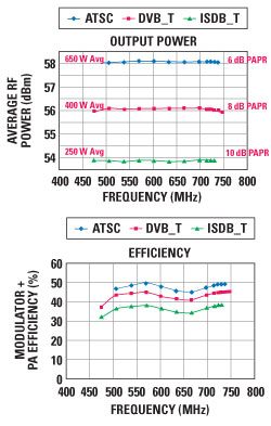
Figure 1 Broadband high power ET PA example.
Why Use ET for Military Applications?
Military success has always depended on effective battlefield communications and with the emerging proliferation of radios, sensors and unmanned assets, this has proved to be an increasing technical challenge. In this environment, it is essential to integrate all battlefield communications within a single integrated network to provide seamless access to voice and data traffic. This objective has been pursued in the U.S. under the JTRS program with the result being a complete networking concept enabled by SDR and several new networking waveforms. In order to understand the benefits ET brings to radios operating in this environment, it is useful to review the top level network architecture and associated waveforms.
In concept, the evolving military communications network has three distinct levels; lower, mid-level and upper, with each level having specific functionality and waveforms commensurate with this functionality. The lower level is intended to support the tactical edge and provides voice and low capacity data services including connectivity to other edge devices. Network domains are formed using the Soldier Radio Waveform (SRW) which fully supports self-forming ad hoc IP networking. At this level, domains are generally small geographically and are supported by small form factor handheld radios with RF transmit powers typically in the range 2 to 5 W.
Networking at the mid-level is by means of the Wideband Networking Waveform (WNW) which again supports self-forming mobile ad hoc networks with each radio being a node on an IP-based mesh. The purpose of the mid-level is to provide effective high capacity backhaul. It provides connectivity between the lower level local networks at the tactical edge and integrates all data over a large geographical area. Radios for use in mid-level communications must therefore have an extended range and simultaneously be able to interconnect to both lower and upper levels. Interconnection with the lower level uses SRW whilst upper level interconnection uses the Mobile User Objective System (MUOS) satellite system. Mid-level radios today are generally man portable or vehicle mounted with RF transmit powers in the 20 to 50 W range. Support for SRW, WNW and MUOS waveforms is therefore required in addition to a range of legacy waveforms. Planned upper level integration of the total networked battlespace will use assets that include WIN-T, the MUOS satellite constellation and GIGBE, and consequently, will be global in scale. See JTNC Newsletter for further background on the communications networks and waveforms discussed here.1
For the emerging military communications strategy to succeed, next generation radios require certain features which are challenging for the radio designer. Each radio is required to support one or more high PAPR waveforms operating over an extended frequency range. Depending on whether the radio is assigned for operation on the lower or mid-level networks, these modern waveforms may have to operate alongside a range of legacy waveforms, imparting additional demands. These considerations create significant challenges for the transmit chain where efficiency and linearity are crucial. In the future, these challenges will be compounded with the move toward cognitive radios required for the DARPA Wireless Network after Next (WNaN) program.
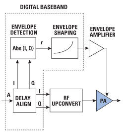
Figure 2 ET-enabled system architecture.
ET exhibits attributes well suited to meeting these requirements. An example of ET’s ability to deliver high efficiency, broadband PAs capable of operating with a wide range of signal PAPRs is shown in Figure 1. This allows the efficiency of broadband PAs to be significantly improved without the inherent RF bandwidth restrictions of RF phasing techniques such as Doherty and Chireix.
ET System Anatomy
A typical ET-enabled transmit system is shown in Figure 2. At the heart of the system is the envelope amplifier (also known as an envelope modulator) that must provide a high efficiency, low noise and high bandwidth dynamic power supply to the PA. Envelope detection and shaping functionality needs to be added to the digital baseband processing in an ET system to generate a reference signal for the envelope amplifier. The envelope shaping determines the relationship between the instantaneous RF power and the PA supply voltage and influences many key metrics of the ET system. Lastly, accurate, stable timing alignment between the RF and envelope signals is necessary to achieve low PA distortion and this function is also typically implemented in the digital baseband.
Modulator Architectures
Examples of basic ET modulator architectures are shown in Figure 3. The first is a fast switcher-only architecture. This simple scheme can achieve ~90 percent efficiency with low power and low bandwidth signals but is difficult to scale up in bandwidth and power. To achieve good TX linearity, the bandwidth of the envelope path has to be 2 to 3 times the RF bandwidth. Furthermore, to achieve good stability margin and switching noise suppression, the ratio between switching rate and modulation bandwidth for a single phase buck converter is typically 10×, resulting in a switching frequency to RF bandwidth ratio of 20 to 30:1. This means that to achieve an RF modulation bandwidth of only 2 MHz, a switching frequency of ~50 MHz is required. Increased switching frequency results in excessive semiconductor switch and inductor losses. Multi-phase/multi-level switch mode techniques can be used to reduce the ratio between switching rate and modulation bandwidth, at the expense of increased complexity.
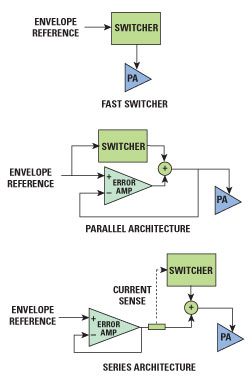
Figure 3 Modulator architectures.
The second architecture is the hybrid parallel switcher-error amplifier architecture. The switcher ‘leads’ by creating a crude approximation of the desired waveform, and a linear amplifier ‘follows’ by cleaning up the output of the switcher. An efficient but relatively low bandwidth switch-mode power supply provides 80 to 90 percent of the power at DC and low frequencies, and the less-efficient but high-bandwidth linear error correction amplifier provides the remaining HF power. In addition to providing the modulator’s HF signal content, the error amplifier also suppresses high frequency switcher noise by comparing the switcher output with the desired reference. Feedback loops around the error amplifier and switcher ensure that the modulator exhibits low output impedance across a wide frequency range – a feature critical to achieving high tracking accuracy and good transmitter linearity. The overall efficiency of the modulator architecture is typically >80 percent and is almost flat with increasing bandwidth – a highly desirable characteristic.
The third is the hybrid series switcher-error amplifier architecture. This comprises a ‘leading’ error amplifier driving the PA supply and a ‘following’ switcher. Current sensing detects when the current drawn from the error amp exceeds a pre-determined threshold and a hysteretic switcher is used to efficiently supply additional current to the PA. At low bandwidths, the overall efficiency of this architecture is similar to the parallel architecture, but the efficiency tends to fall with increasing signal bandwidth as delays in the switcher loop result in the switcher working against the linear amplifier. In addition, the switcher ripple current has to flow into the low impedance output of the linear amplifier, resulting in increased linear amplifier dissipation.
More complex derivatives of both the parallel and series hybrid architectures are possible. These generally use multi-phase and/or multi-level switchers to increase modulator efficiency, provide voltage boost capability or increase bandwidth. Low power (~750 mW average RF) handset modulator ASICs providing high efficiency and voltage boost capability are becoming available. One such ET IC uses a single phase buck converter to provide the DC and LF power, and a multiphase, multilevel converter to provide the bulk of the remaining power. A linear error amplifier is used to clean up the switching noise of the switch-mode converters. Such ASICs operate with standard 2.5 to 5.25 V Li-ion batteries and generate a 4.5 V peak/1.2 A peak PA supply capable of supporting RF bandwidths up to 20 MHz.
High-density IC components incorporating all necessary ET functions for medium-power mobile applications (~5 to 25 W average RF) are also emerging. For instance, all signal processing and DAC functions may be integrated on one IC whilst a second IC may integrate several switcher controllers. At this power level, external O/P stages may be used to allow the power and voltage range of the modulator to be optimized to suit the PA voltage and power. Compact scalable ET modulators fit into satcoms and higher-power handset applications, in addition to low-power vehicle-mounted terminals. At this power level, a typical modulator may operate from 10 to 30 V supplies to generate a 10 to 30 V peak/1 A peak PA supply capable of supporting RF bandwidths up to 20 MHz.
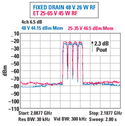
Figure 4 Increased O/P power capability using ET.
Benefits of ET-Enabled PAs
A fixed-supply PA only operates in compression during infrequent waveform peaks, whereas an ET PA operates in compression most of the time. This results in ET PAs operating more efficiently and with lower die powers, enabling smaller PA devices and smaller, lighter batteries to be used for a given system capability.
The PA die size is primarily determined by the system peak power requirements and is in principle the same for both fixed supply and ET having the same peak voltage. However, the use of ET greatly reduces die power dissipation and temperature which often results in further increased peak power capability. In addition, for GaN devices the peak power capability may be significantly increased by operating in ET mode, allowing a higher peak supply voltage than could be sustained in fixed supply operation. This is possible because the output power in fixed supply mode is often limited by thermal issues rather than voltage considerations. In the example shown in Figure 4, the peak output power of a fixed drain 48 V GaN PA increased by 2.3 dB when operated in ET mode with 25 to 65 V swing range. Despite the increased RF output power, the die power dissipation actually decreased from 45 to 32 W.
The reduction in PA die power dissipation reduces heat sinking requirements, simplifying the thermal design. This can eliminate the need for fans, heat pipes, heat sink fins, etc., reducing product size, weight and cost.
A perhaps unexpected benefit of ET is increased VSWR tolerance compared with fixed supply PAs. The increasing use of wideband PAs and wideband antennas means that the antenna match is often not ideal and may vary dynamically in use. In these situations, a fixed-supply PA would need to operate with significant power back-off to maintain linearity. But it is found that ET PAs can work into high VSWR loads with significantly less ACPR degradation. The explanation for this initially surprising finding may be found in the fact that an ET PA operates in compression over much of the envelope cycle by design, using a shaping table chosen to achieve flat AM-AM characteristics. If exposed to a VSWR phase angle that results in a significantly higher load impedance, it operates in even heavier compression, but the shaping table still results in approximately flat AM-AM characteristics – i.e., the PA linearity does not alter dramatically. In contrast, the AM-AM characteristics of a fixed supply PA will be considerably altered when working into load impedances higher than intended (see Figure 5).
The provision of a fall-back Average Power Tracking (APT) mode means that ET PAs can also offer high efficiency when operating with legacy low bandwidth, constant envelope or low PAPR waveforms, or when operating at low power with backed-off high PAPR waveforms. This APT mode is generally accomplished by disabling the linear amplifier of a hybrid modulator and running only the switcher. This then generates a variable voltage fixed DC output with an efficiency of 90 to 95 percent so that the PA runs with the minimum fixed-supply necessary to reproduce the legacy waveform with adequate linearity.
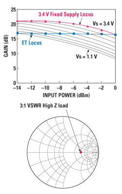
Figure 5 ET and fixed supply operation into mismatched load.
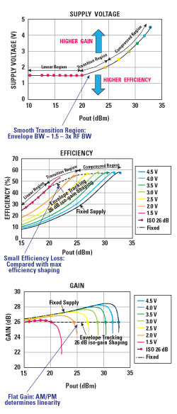
Figure 6 ISOgain shaping.
ET PA Characteristics
As previously noted, the shaping function plays an important role in determining many key metrics of an ET PA system. To understand why, it is necessary to appreciate some of the fundamental efficiency and linearity characteristics of the PA itself. A traditional fixed supply is usually considered to be a two port device whose fundamental output characteristics (efficiency, gain, phase, etc.) are a function of only a single input variable, the instantaneous input RF voltage. An ET PA may be considered to be a three port device whose output characteristics are determined by both instantaneous input power and supply voltage. Surface plots are therefore required to properly understand its ET mode behavior. The operating trajectory across the output surfaces is determined by the shaping function, which determines the nonlinear mapping between instantaneous input RF voltage and supply voltage.
Three operating regions may be identified for a typical ET PA as shown in Figure 6. At high instantaneous power, in the compressed region, the PA’s output characteristics are determined by the supply voltage. At low instantaneous power, in the linear region, the PA operates as a conventional fixed supply PA and its output characteristics are determined by RF input voltage. In between these, in the transition region, the PA’s characteristics depend on both supply voltage and RF input voltage. The choice of shaping function determines the trade-off between the efficiency and compression characteristics of the PA and determines the transition points between operating regions. Figure 6 illustrates that it is possible to select a shaping function that results in a flat PA gain characteristic (ISOgain), with only a slight impact on its efficiency. Hence ET offers the possibility of a simple method for linearizing the AM characteristics of a PA whilst simultaneously raising its efficiency. The AM-PM characteristics are not directly controllable by the shaping function in the same way, so to fully exploit this linearization benefit, the PA should be designed to show low intrinsic AM-PM.
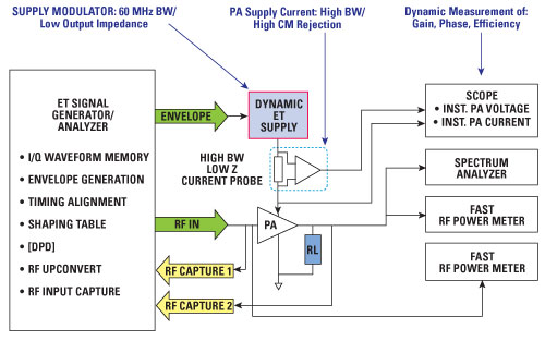
Figure 7 PA characterization.
To determine the ET shaping function, the PA must first be characterized under representative operating conditions. So how can the PA be measured? It might initially be thought that a VNA power sweep to capturing AM-AM and AM-PM data across a range of supply voltages would be adequate. Unfortunately, data captured in this way results in poor ET performance prediction on account of die heating effects due to the slow CW sweep. A better characterization can be achieved using a setup like that shown in Figure 7. The key elements of this setup are an ET signal source which generates time synchronized RF and envelope waveforms, and a dynamic power supply which generates the PA supply voltage. Simultaneous captures of the instantaneous input and output RF power, together with instantaneous supply voltage and supply current, enable the key PA characteristics to be captured under representative operating conditions.
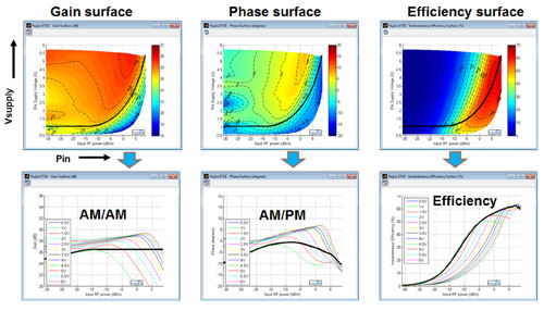
Figure 8 ET PA characterization and shaping function derivation.
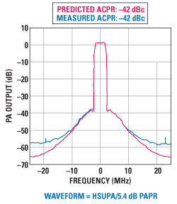
Figure 9 ET performance prediction from ET PA characteristics.
Once this raw data has been captured, it may be post-processed in many ways to examine different aspects of ET PA performance. Three particularly useful surfaces (gain, phase and efficiency) are shown in Figure 8. In these plots, color-mapped contours of constant gain, phase and efficiency are represented by the z direction. The shaping function – the mapping between instantaneous input power and supply voltage – is overlaid as a black line on all three plots. Once this is determined, more familiar 2D plots of the PA’s AM-AM, AM-PM and instantaneous efficiency may be derived, as shown in Figure 8.
These metrics are useful as they give considerable insight into mechanisms that may be limiting linearity or efficiency performance. Typically, however, PA specifications are defined by system level parameters such as ACPR, EVM and average efficiency. Further post-processing of the instantaneous AM-AM, AM-PM and efficiency data together with knowledge of the target waveform may be used to predict these parameters also. This is shown in Figure 9 which shows a comparison of predicted ACPR based on PA characterization and waveform data, and measured results using the actual waveform.
This begs the question of how a PA should be designed to achieve good ET performance, particularly where the target application cannot support the complexity and power overhead of sophisticated closed loop DPD linearity correction. Figure 10 shows the AM-AM or gain characteristics of an ET optimized PA. To achieve flat gain as shown by the dotted black line, the PA operates in moderate compression at high instantaneous power and gradually comes out of compression as the instantaneous power reduces. It is important that the gain at very low powers and low supply voltage is flat, and that the low supply voltage small signal gain is less than the high supply voltage small signal gain. If this is not the case, the ET PA will exhibit gain recovery at low instantaneous power, resulting in wideband TX distortion due to the high rate of change of signal at low power. It is interesting to note that the PA compression characteristics of a traditional fixed supply PA are of little relevance to an ET PA, as the PA never operates in this region.
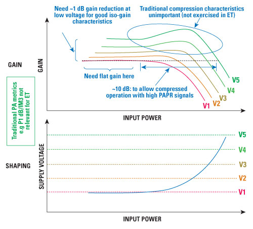
Figure 10 ET PA – ideal characteristics.
ET System Performance Optimization
Murphy’s Law for PAs dictates that there is always some trade-off between system efficiency and linearity, hence it usually makes sense to trade linearity for efficiency to just meet the TX linearity target with adequate margin. In high power systems, this can be achieved through use of baseband crest factor reduction (CFR). However, this is computationally intensive, and ET allows a crude form of CFR to be implemented simply by modifying the contents of the shaping table as shown in Figure 11. The level and ‘sharpness’ of the soft clipping may be used to provide a degree of control over how far from carrier the inevitable distortion products lie. By reducing the PAPR of the PA output signal, this technique enables the PA to operate at high average power, increasing system efficiency.
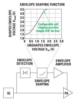
Figure 11 Shaping table based crest factor reduction.
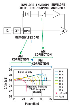
Figure 12 Combined RF pre-correction + shaping function linearization.
It has been shown that ET may be used to linearize a PA in addition to improving its efficiency; however, this may necessitate use of a wider supply voltage swing range than is needed to achieve best efficiency from the PA/supply modulator combination, particularly if the PA has not been well optimized for ET operation. Where this is the case, it can make sense in low and medium power systems to include simple RF pre-correction – a cut-down version of traditional DPD – allowing the minimum supply voltage to be optimized for best efficiency. In this architecture, shown in Figure 12, envelope shaping is used to control AM at high instantaneous powers and RF path pre-correction is used to provide AM correction at low instantaneous powers and PM correction across the entire power range.
Conclusion
With the move to networked combat data services driving the demand for higher data rates, envelope tracking satisfies the diverse requirements of next generation military radio transmitters. ET-enabled PAs allow for the use of smaller power sources or longer battery life, together with lower cooling requirements resulting in lighter, smaller radios. They can handle the range of waveform types from legacy voice to high-capacity data, offer broadband RF capability, and have improved linearity and antenna mismatch tolerance.
Reference
- JTNC Newsletter Vol. 1, Issue 1, March 2013.