
A compact wide stopband bandpass filter, based on composite right/left handed transmission line (CRLH-TL), is proposed in this article. The prototype filter has a wide stopband performance, a compact size and low insertion loss in the passband. A backside aperture is applied below the inter-digital part to realize a strong coupling between the fingers. The filter achieves a sharp stopband at both sides of the passband and low insertion loss within the passband. The properties of CRLH-TL enable the spurious responses to emerge far away from the passband of the bandpass filter. To further improve its upper stopband, two U-shaped defected ground structures (DGS) are placed at the input and output feed lines, respectively. Both filters are designed, simulated and fabricated. The measured results show good agreement with the simulated ones.
Figure 1 Schematic view of the proposed filter (a) top view and (b) bottom view.
A bandpass filter is one of the key passive components in the design of microwave communication systems and various types of bandpass filters that have been reported and investigated.1-17 Recently, there has been a significant interest in composite right/left handed transmission line (CRLH-TL) and a lot of passive circuits and antennas have been designed based on this structure.18-34 Unlike the conventional transmission line, CRLH-TL offers some unique characteristics and is very useful in practical applications. CRLH-TL has been used to design couplers;18-20 leaky-wave antennas with backward and forward scanning capability were realized by using CRLH-TL;21-24 and the concept of the zeroth- and negative-order resonance has been proposed, based on the CRLH-TL,25-26 and were utilized to design novel antennas and filters.
CRLH-TL has provided a new way for microwave resonator design and it has been demonstrated as a good choice for size reduction both theoretically and practically.25-29 Besides, its nonlinear electric response ensures a wide stopband. A CRLH-TL based filter using coplanar waveguide (CPW) has been proposed.28 Though a wide stopband is obtained, the high insertion loss makes it difficult for practical application. A CRLH-TL based filter has been proposed.29 The author has used a conventional CRLH-TL unit, with one side open circuited and the other side short circuited, to realize a quarter-wave type resonator. Though the quarter-wave type resonator is half the size of a half-wave type resonator in the traditional transmission line concept, the resonator implemented by CRLH-TL does not offer size reduction, compared with a conventional CRLH-TL half-wave type resonator. Moreover, many shorted via holes are required in the structure, which increases the difficulty for fabrication.
In this article, a second order, wide stopband, bandpass filter is proposed. The modified CRLH-TL resonator is introduced to obtain a stronger electric coupling. To further broaden its upper stopband, a U-shaped slot is employed to suppress the spurious passband. Both filters are carefully designed, optimized and fabricated. The measured results show good agreement with the simulated ones.
Design Approach
Figure 1 shows the configuration of the proposed filter. Two resonators are involved to realize two transmission poles in the passband. The resonator is composed of an interdigital capacitance and a short ended line as the shunt inductance. To realize a strong coupling between the fingers, the ground plane underneath the interdigital strips is removed to form a backside aperture. Based on the composite right/left handed transmission line theory, the resonator is open circuited at both ends. Its closed-form dispersion relation for the periodic implementation can be expressed by:35

where p stands for the size of the structure, so the electric length can be expressed by:

The half-wavelength transmission line resonates when

Figure 2 Equivalent circuit of the proposed bandpass filter.
The equivalent circuit model for the proposed bandpass filter is depicted in Figure 2. The electric coupling should be the dominating coupling mechanism between the two resonators. The grounded series resonators symmetrically located near the input and output ports are used to get the transmission zero generated by the feed lines. The values of the inductors and capacitors are shown in Table 1 and the calculated scattering parameters are shown in Figure 3. As shown, a second order Chebyshev response is obtained. The filter operates at 2.7 GHz and the transmission zero located at 5.6 GHz is due to the grounded series resonator, which can be explained by the resonance of the feed lines.
Figure 3 Calculated S-parameters for the circuit in Figure 2.
The filter can also be designed with the coupled resonator circuit method. The ideal [N+2] coupling matrix is derived as follows:
The external quality value can be computed from the coupling matrix as:

Simulations and Measurements
The proposed filter is fabricated on a Taconic RF-35 substrate with a dielectric constant of 3.5 and a thickness of 0.508 mm. A simulation tool (Zeland IE3D) is used to optimize the proposed filter. The final optimized sizes and parameters of the wide-stopband bandpass filter are: Ll = 12.8 mm, W1 = 0.9 mm, Lc = 3.2 mm, Wc = 0.2 mm, s = d = 0.1 mm, Wl = 0.2 mm, d1 = 0.1 mm and D = 0.5 mm.
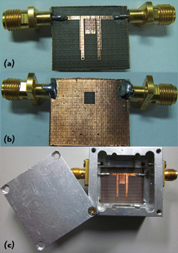
Figure 4 Photograph of the fabricated filter (a) top view, (b) bottom view and (c) packaged.
Figure 4 shows a photograph of the fabricated filter in a metal housing. There is a 3 mm gap between the substrate and the housing. The filter has a compact size of 0.05 × 0.21 λg (6.1 × 12.8 mm), where λg is the guided wavelength at center frequency of the passband. The performance of the fabricated BPF was measured using an Agilent 8757D network analyzer. As shown in Figure 5, the filter operates at 2.7 GHz and has a 3 dB bandwidth of approximately 200 MHz. The fabricated bandpass filter has a wide upper stopband with more than 15 dB attenuation from 3.2 to 13.3 GHz. Besides, the measured insertion loss in the passband is only 0.99 dB, which is very remarkable in microstrip line filters.
Figure 5 Simulated and measured S-parameters of the filter.
Figure 6 Schematic view of the filter with U-shaped DGS (a) top view and (b) bottom view.
To further broaden the upper stopband of the filter, the U-shaped defected ground structure (DGS) is employed to suppress the spurious response of the structure. The U-shaped DGS is etched below the input/output feed lines symmetrically, as shown in Figure 6. The U-shaped DGS structure can generate a transmission zero at its resonance frequency and then it can be used to suppress the spurious response. The dimensions of the added U-shaped DGS are Ls = 7.7 mm, Ws = 0.1 mm. The final simulated and fabricated results demonstrate that the added U-shaped DGS works well. Figure 7 shows the photograph of the fabricated filter with DGS, also in a packaged cavity.
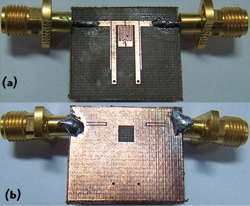
Figure 7 Photographs of the fabricated filter with DGS (a) top view and (b) bottom view.
Figure 8 Measured and simulated S-parameters of the filter with DGS.
The measured results in Figure 8 (also taken with an Agilent 8757D network analyzer) show that the filter achieves a wide upper stopband with more than 15 dB attenuation up to 16.4 GHz, and performance of the filter with U-shaped DGS is almost the same as the above filter without U-shaped DGS, except that the insertion loss is slightly worsened to 1.07 dB.
Conclusion
In this article, a CRLH-TL based bandpass filter is proposed. To further extend the upper stopband, a U-shaped DGS is employed. Both the equivalent circuit method and the coupled resonator circuit method have been applied for the analysis of the filter. The final fabricated filter has a compact size, wide upper stopband and low insertion loss. The good performance makes it practical for microwave applications.
Acknowledgment
The work for this grant was supported by the National Natural Science Foundation of China (Grant No: 61271026), by the National Natural Science Foundation of China-NSAF (Grant No: 10976005), by the Program for New Century Excellent Talents in University (Grant No: NCET-11-0066) and by the Research Fund of Shanghai Academy of Spaceflight Technology (SAST201243).
References
- L. Ma, K. Song, C.L. ZhuGe and Y. Fan, “Compact Bandpass Filter with Wide Upper-stopband Based on Spiral-shaped Resonators and Spur-lines,” Progress in Electromagnetics Research Letters, Vol. 29, 2012, pp. 87-95.
- J.T. Kuo, S.C. Tang and S.H. Lin, “Quasi-Elliptic Function Bandpass Filter with Upper Stopband Extension and High Rejection Level Using Cross-Coupled Stepped-Impedance Resonators,” Progress in Electromagnetics Research, Vol. 114, 2011, pp. 395-405.
- K. Song and Q. Xue, “Inductance-Loaded Y-Shaped Resonators and Their Applications to Filters,” IEEE Transactions on Microwave Theory and Techniques, Vol. 58, No. 4, April 2010, pp. 978-984.
- G. Chaudhary, Y. Jeong, K. Kim and D. Ahn, “Design of Dual-band Bandpass Filters with Controllable Bandwidths Using New Mapping Function,” Progress in Electromagnetics Research, Vol. 124, 2012, pp. 17-34.
- J.T. Kuo, C.Y. Fan and S.C. Tang, “Dual-wideband Bandpass Filters with Extended Stopband Based on Coupled-line and Coupled Three-Line Resonators,” Progress in Electromagnetics Research, Vol. 124, 2012, pp. 1-15.
- K. Song and Q. Xue, “Compact Ultra-wideband (UWB) Bandpass Filters with Multiple Notched Bands,” IEEE Microwave and Wireless Components Letters, Vol. 20, No. 8, August 2010, pp. 447-449.
- P.Y. Hsiao and R.M. Weng, “Compact Tri-Layer Ultra-Wideband Bandpass Filter with Dual Notch Bands,” Progress in Electromagnetics Research, Vol. 106, 2010, pp. 49-60.
- J.Q. Huang and Q.X. Chu, “Compact UWB Band-pass Filter Utilizing Modified Composite Right/Left-handed Structure with Cross Coupling,” Progress in Electromagnetics Research, Vol. 107, 2010, pp. 179-186.
- K. Song and Q. Xue, “Compact Ultra-wideband Bandpass Filter Using Dual-line Coupling Structure,” IEEE Microwave and Wireless Components Letters, Vol. 19, No. 1, January 2009, pp. 548-550.
- H.B. Qin, Y.W. Zhai and Y.J. Zhao, “Synthesis Method for Chebyshev Dual-Band Microwave Filters,” Journal of Electromagnetic Waves and Applications, Vol. 24, No. 2-3, 2010, pp. 307-317.
- K. Song and Q. Xue, “Novel Broadband Bandpass Filters Using Y-Shaped Dual-Mode Microstrip Resonators,” IEEE Microwave and Wireless Components Letters,Vol. 19, No. 9, November 2009, pp. 548-550.
- S.G. Mo, Z.Y. Yu and L. Zhang, “Design of Triple-mode Bandpass Filter Using Improved Hexagonal Loop Resonator,” Progress in Electromagnetics Research Letters, Vol. 96, 2009, pp. 117-125.
- O. Garcia-Perez, L.E. Garcia-Munoz, D. Segovia-Vargas and V. Gonzalez-Posadas, “Multiple Order Dual-band Active Ring Filters with Composite Right/Left-handed Cells,” Progress in Electromagnetics Research, Vol. 104, 2010, pp. 201-219.
- A.M. Abu-Hudrouss and M.J. Lancaster, “Design of Multiple-band Microwave Filters Using Cascaded Filter Elements,” Journal of Electromagnetic Waves and Applications, Vol. 23, No. 16, 2009, pp. 2109-2118.
- X.Q. Lin, Q. Cheng, R.P. Liu, D. Bao and T.J. Cui, “Compact Resonator Filters and Power Dividers Designed with Simplified Meta-Structures,” Journal of Electromagnetic Waves and Applications, Vol. 21, No. 12, 2007, pp. 1663-1672.
- D. Ni, Y. Zhu, Y. Xie and P. Wang, “Synthesis and Design of Compact Microwave Filters with Direct Source-load Coupling,” Journal of Electromagnetic Waves and Applications, Vol. 20, No. 13, 2006, pp. 1875-1885.
- K. Song, Y. Fan and Y. Zhang, “Modeling and Application of Stepped Impedance Resonators with Double Coaxial Structure,” Microwave and Optical Technology Letters, Vol. 48, No. 11, 2006, pp. 2314-2317.
- C. Caloz, A. Sanada and T. Itoh, “A Novel Composite Right-/left-handed Coupled-line Directional Coupler with Arbitrary Coupling Level and Broad Bandwidth,” IEEE Transactions on Microwave Theory and Techniques, Vol. 52, No. 3, March 2004, pp. 980-992.
- H.V. Nguyen and C. Caloz, “Generalized Coupled-mode Approach of Metamaterial Coupled-line Couplers: Coupling Theory, Phenomenological Explanation and Experimental Demonstration,” IEEE Transactions on Microwave Theory and Techniques, Vol. 55, No. 5, May 2007, pp. 1029-1039.
- A. Hirota, Y. Tahara and N. Yoneda, “A Compact Forward Coupler Using Coupled Composite Right-/left-handed Lines,” IEEE Transactions on Microwave Theory and Techniques, Vol. 57, No. 12, December 2009, pp. 3127-3133.
- Y. Chen, S.W. Liao, J. Wei, and J.H. Xu, “Unequally Spaced and Excited Resonant Slotted-waveguide Antenna Array Based on an Improved Resonant-slot Coupled Cavity Chain Composite Right/left-handed Waveguide,” Progress in Electromagnetics Research, Vol. 110, 2010, pp. 421-435.
- S. Lim, C. Caloz and T. Itoh, “Electronically Scanned Composite Right/left- handed Microstrip Leaky-wave Antenna,” IEEE Microwave and Wireless Components Letters, Vol. 14, No. 6, June 2004, pp. 277-279.
- S. Lim, C. Caloz and T. Itoh, “Metamaterial-based Electronically Controlled Transmission-line Structure as a Novel Leaky-wave Antenna with Tunable Radiation Angle and Beamwidth,” IEEE Transactions on Microwave Theory and Techniques, Vol. 53, No. 1, January 2005, pp. 161-173.
- F.P. Casares-Miranda, C. Camacho-Penalosa and C. Caloz, “High-gain Active Composite Right/left-handed Leaky-wave Antenna,” IEEE Transactions on Antennas and Propagation, Vol. 54, No. 8, August 2006, pp. 2292–2300.
- J.G. Lee and J.H. Lee, “Zeroth Order Resonance Loop Antenna,” IEEE Transactions on Antennas and Propagation, Vol. 55, No. 3, March 2007, pp. 3710-3712.
- S.G. Mao, M.S. Wu, Y.Z. Cue and C.H. Che, “Modeling of Symmetric Composite Right/left-handed Coplanar Waveguides with Applications to Compact Bandpass Filters,” IEEE Transactions on Microwave Theory and Techniques, Vol. 53, No. 11, November 2005, pp. 980-992.
- J.L. Jimenez Martin, V. Gonzalez-Posadas, J.E. Gonzalez-Garcia, F.J. Arques-Orobon, L.E. Garcia-Munoz and D. Segovia-Vargas, “Dual Band High Efficiency Class C Power Amplifier Based on CRLH Diplexer,” Progress in Electromagnetics Research, Vol. 97, 2009, pp. 217-240.
- A. Sanada, C. Caloz and T. Itoh, “Novel Zeroth-order Resonance in Composite Right/left-handed Transmission Line Resonators,” 2003 Asia–Pacific Microwave Conference Proceedings, Vol. 3, pp. 1588-1593.
- T. Yang, M. Tamura and T. Itoh, “Compact Hybrid Resonator with Series and Shunt Resonances Using in Miniaturized Filters and Balun Filters,” IEEE Transactions on Microwave Theory and Techniques, Vol. 58, No. 2, February 2010, pp. 390-402.
- X.Q. Lin, P. Su, Y. Fan and Z.B. Zhu, “Improved CRLH-Tl with Arbitrary Characteristic Impedance and its Application in Hybrid Ring Design,” Progress in Electromagnetics Research, Vol. 124, 2012, pp. 249-263.
- G. Monti, R. De Paolis and L. Tarricone, “Design of a 3-State Reconfigurable CRLH Transmission Line Based on Mems Switches,” Progress in Electromagnetics Research, Vol. 95, 2009, pp. 283-297.
- A.F. Abdelaziz, T.M. Abuelfadl and O.L. Elsayed, “Realization of Composite Right/left-handed Transmission Line Using Coupled Lines,” Progress in Electromagnetics Research, Vol. 92, 2009, pp. 299-315.
- Y. Li, Q. Zhu, Y. Yan, S.J. Xu and B. Zhou, “Design of a 1*20 Series Feed Network with Composite Right/left-handed Transmission Line,” Progress in Electromagnetics Research, Vol. 89, 2009, pp. 311-324.
- J.X. Niu and X.L. Zhou, “Analysis of Balanced Composite Right/left Handed Structure Based on Different Dimensions of Complementary Split Ring Resonators,” Progress in Electromagnetics Research, Vol. 74, 2007, pp. 341-351.
- C. Caloz, C. Allen and T. Itoh, “Unusual Propagation Characteristics in CRLH Structures,” 2004 IEEE Antennas and Propagation Society International Symposium Digest, Vol. 4, pp. 3549-3552