
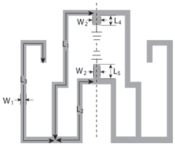
Figure 1 Layout of the proposed short stub loaded resonator.
A compact microstrip triple-band bandpass filter (BPF), using a multimode short stub loaded resonator and two λ/2 side-coupled resonators, is proposed in this article. The characteristics of the multimode resonator are investigated by using even and odd mode analysis. This filter’s three passband frequencies and their bandwidths can be designed and tuned independently. For demonstration purposes, a filter with triple-band elliptic response operating at 2.45 GHz (ISM band), 3.5 GHz (WiMAX band), and 5.75 GHz (WLAN band) was designed, fabricated and measured. The measured results are in good agreement with the full-wave simulation results.
With the increasing demands for triple-band applications in modem wireless systems, research on innovative designs of triple-band filters has become very popular recently. Configurations of composite split-ring resonators (SRR) have been used to design a triple-band filter.1 A triple-band bandpass filter (BPF) has been proposed using three pairs of degenerate modes in a ring resonator.2 A square ring loaded resonator (SRLR) has been proven in the design of a triple-band filter.3 The SRLR can generate a triple-band response by tuning its geometric parameters to realize the high-order tri-band. The square ring short stub loaded resonators (SRSLR) have been introduced for the design of the tri-band filter.4 The passband frequencies can be conveniently tuned to the desired values by controlling the corresponding resonator dimensions. Tri-band BPFs can also be constructed using several stepped-impedance resonators (SIR).5-7
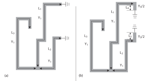
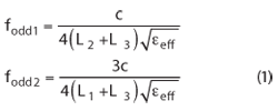
Figure 2 Equivalent circuits (a) odd-mode and (b) even-mode.
In this article, the tri-band performance is realized by using a multimode short stub loaded resonator and two λ/2 side-coupled resonators, which are arranged in a compact structure.The passband frequencies and their bandwidths can be independentlytuned to the desired values by controlling the corresponding parametersdimensions. For demonstration, a prototype is designed, fabricated and measured.
Proposed Short Stub Loaded Resonator
As shown in Figure 1, the proposed short stub loaded resonator consists of a ring resonator with two short stubs and two open folded microstrip lines. Since the resonator is even symmetrical to the dashed line, its resonant characteristics can be examined by the even- and odd-mode method. The odd-mode and even-mode equivalent circuits are shown in Figure 2. The odd-mode equivalent circuit contains two resonant circuits. The two odd-mode resonant frequencies can be obtained as follows:3
where c is the speed of light in free space and εeff is the effective dielectric constant of the substrate.
Y1 and Ys are the characteristic admittances of the lines with widths W1 and W2. Y1 is set equal to Ys/2 for simplicity. For the even-mode excitation, the resonant frequencies can be obtained as:
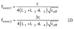
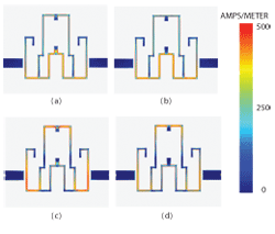
Figure 3 Simulated electric current density.
From Equations 1 and 2, it can be seen that the first passsband can be determined by L2 and L3 and its bandwidth is tuned by L5. Similarly, the second passsband may be given by L1 and L3 and its bandwidth is changed by L4. Thus, by reasonably designing the parameters L1, L2 and L3, the dual-band frequencies are approximately allocated in the suitable passbands and their bandwidths can be independently modified by varying L4 and L5, respectively. For demonstration purpose, this resonator is simulated by Sonnet 11.54 and the simulated electric current densities of the four modes are presented in Figure 3, with W1 = 0.3 mm, W2 = 0.6 mm, L1 = 12.4 mm, L2 = 6.5 mm, L3 = 10.58 mm, L4 = 0.7 mm, L5 = 1.08 mm and feven1 = 2.50 GHz (a), fodd1 = 2.68 GHz (b), feven2 = 5.47 GHz (c), fodd2 = 5.7 GHz (d).
Tri-band BPF Design and Results
Figure 4 describes the layout of the designed filter. This filter is composed of a single short stub loaded resonator and a pair of half-wavelength (λ/2), side-coupled resonators, with length L6 + L7 and width W1. The former is used to generate two passbands for dual-mode dual-band BPF design. The latter is applied to generate the third passband for two-pole BPF design and its bandwidth can be tuned by the gap g1.8 Also, the pair of side-coupled resonators encircles the short stub loaded resonator and serves as part of feed lines, so that a compact size is realized.
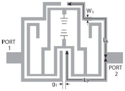
Figure 4 Schematic of the proposed tri-band BPF.
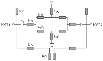
Figure 5 Equivalent circuit of the proposed tri-band BPF.
This triple-band filter was fabricated on a substrate with a relative dielectric constant of 4.5 and a thickness of 0.8 mm. The dimensions of the filter are optimized as follows: W1 = 0.3 mm, W2 = 0.6 mm, L1 = 12.4 mm, L2 = 6.5 mm, L3 = 10.58 mm, L4 = 0.7 mm, L5 = 1.08 mm, L6 = 11.6 mm, L7 = 12.91 mm, g1 = 0.4 mm. Figure 5 shows the equivalent circuit of the proposed tri-band BPF. The capacitor C1 simulates the coupling strength between the half-wavelength (λ/2) side-coupled resonators and the proposed short stub loaded resonator. Figure 6 shows a comparison of the equivalent circuit simulation (Ansoft Designer) and EM simulation (Sonnet 11) for the proposed filter. The equivalent circuit simulation result is in good agreement with the EM-simulation result.
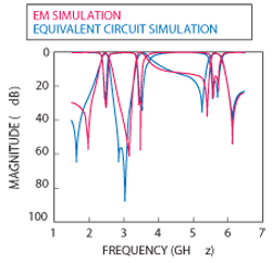
Figure 6 Simulated responses of the proposed filter.
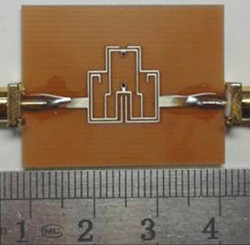
Figure 7 Photograph of the fabricated tri-band filter.
A photograph of the fabricated tri-band filter is shown in Figure 7.The measured and EMsimulated results are illustrated in Figure 8. Three pairs of transmission poles appear at 2.47/2.52, 3.4/3.49 and 5.58/5.72 GHz. The measured 3 dB fractional bandwidths for the three passbands (2.45, 3.5 and 5.75 GHz) are found to be 10.2, 11.4 and 5.56 percent, respectively. The measured minimum insertion losses are 1.1, 1.21 and 1.3 dB, while the return losses are better than 34.6, 24.1 and 15.2 dB, respectively. Four transmission zeros are created at 2.03, 3.15, 5.4 and 6.2 GHz, resulting in high selectivity.
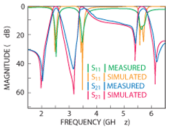
Figure 8 Measured and EM simulated results.
Conclusion
In this article, a compact triple-band BPF is introduced, which has good triple passband performance at 2.45, 3.5 and 5.75 GHz. The three passband frequencies and bandwidths of this filter can be tuned independently by properly controlling the parameters dimensions of these resonators. The measured results are in good agreement with the simulations, verifying this design. This compact triple-band filter is particularly suitable for multi-band and multi-service applications in communication systems.
Acknowledgments
This work was supported by the National Science Foundation of China (No. 61061001) and the 555 Talent Program of Jiangxi Province of China.
References
1. R.H. Geschke, B. Jokanovic and P. Meyer, “Filter Parameter Extraction for Triple-Band Composite Split-Ring Resonators and Filters,” IEEE Transactions on Microwave Theory and Techniques, Vol. 59, No. 6, June 2011, pp. 1500-1508.
2. S. Luo, L. Zhu and S. Sun, “Compact Dual-Mode Triple-Band Bandpass Filters Using Three Pairs of Degenerate Modes in a Ring Resonator,” IEEE Transactions on Microwave Theory and Techniques, Vol. 59, No. 5, May 2011, pp. 1222-1229.
3. J.Z. Chen, N. Wang, Y. He and C.H. Liang, “Fourth-order Tri-band Bandpass Filter Using Square Ring Loaded Resonators,” Electronics Letters, Vol. 47, No. 15, July 2011, pp. 858-859.
4. M.T. Doan, W.Q. Che and W.J. Feng, “Tri-band Bandpass Filter Using Square Ring Short Stub Loaded Resonators,” Electronics Letters, Vol. 48, No. 2, January 2012, pp. 106-107.
5. F. Liang, B. Luo and W.Z. Lu, “Novel Triple-bandpass Microstrip Filter with Flexible Passband Assignment,” Microwave and Optical Technology Letters, Vol. 53, No. 9, September 2011, pp. 2064-2066.
6. H.W. Deng, B. Liu, Y.J. Zhao, W. Chen and X.S. Zhang, “Compact and High Selectivity Triple-band Dual-mode Microstrip BPF with Two Short-circuited Stub-loaded SIRs,” Microwave and Optical Technology Letters, Vol. 54, No. 3, March 2012, pp. 719-721.
7. B.J. Chen, T.M. Shen and R.B. Wu, “Design of Tri-band Filters with Improved Band Allocation,” IEEE Transactions on Microwave Theory and Techniques, Vol. 57, No. 7, July 2009, pp. 1790-1797.
8. J.S. Hong and J.L. Michael, “Couplings of Microstrip Square Open-loop Resonators for Cross-coupled Planar Microwave Filters,” IEEE Transactions on Microwave Theory and Techniques, Vol. 44, No. 11, November 1996, pp. 2099-2109.
Haiwen Liu received his B.S. degree in electronic system and his M.S. degree in radio & remote-sensing science from Wuhan University, Wuhan, China, in 1997 and 2000, respectively. He received his PhD degree from Shanghai Jiaotong University, China, in 2004. From 2004 to 2006, he was with Waseda University, Japan, as a full-time assitant professor. From 2006 to 2007, he was with the Technische Universitat Hamburg-Harburg and Kiel University, Germany, as a Humboldt research fellow. From 2007 to 2008, he was a professor at the Institute of Optics and Electronics, Chinese Academy of Sciences (CAS), Chengdu, China. Since 2009, he is a professor at the School of Information Engineering, East China Jiaotong University, Nanchang, China. His main areas of research are radio system, RF/microwave IC design.
Jiuhuai Lei received his B.S. degree in communication engineering from East China Jiaotong University, Nanchang, China, in 2011. Currently, he is studying for a Master’s degree at the Electromagnetism and Information Technology Institute, East China Jiaotong University, Nanchang, China.
Yulong Zhao received his B.S. degree in electronic information engineering from PLA Information Engineering University, Henan, China, in 2010. Currently, he is studying for a Master’s degree at the Electromagnetism and Information Technology Institute, East China Jiaotong University, Nanchang, China.
Wenyuan Xu received his B.S. degree in optical information science and technology from East China Jiaotong University, Nanchang, China, in 2010. Currently, he is studying for his Master’s in Electromagnetism and Information Technology Institute, East China Jiaotong University, Nanchang, China.