
Until recently, there was no significant solution available on the market for power measurements on wideband sources up to 110 GHz, or for level calibration of network analyzers that have 1 mm test ports. The available V- and W-Band power sensors cover only the signal components within their respective frequency band, which means that users need multiple, harmonized sensors to perform measurements over wide frequency ranges. In contrast, the new R&S NRP-Z58 thermal power sensor provides complete coverage of the entire frequency range from DC to 110 GHz. It is also considerably lighter and easier to work with than power sensors with waveguide connectors.
When looking for power sensors that can be used for applications in the millimeter-wave range, the selection is very small. This is especially true for the frequency range from 67 to 75 GHz and for W-Band (75 to 110 GHz). Also, those sensors that are available cannot be used to detect signals below the cut-off frequency for the type of waveguide used by the sensors, for example. This makes it difficult to perform power measurements on wideband sources such as photodetectors and photoreceivers for the 100 G Ethernet.
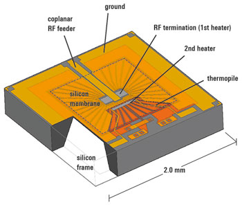
Figure 1 Structure of the thermoelectric transducer.
Similar problems exist for level calibration of network analyzers having 1 mm test ports. Previously, the only possibility was to measure individual frequency ranges sequentially using the appropriate power sensor for that range. In addition, an adapter was needed between a waveguide power sensor and the coaxial connector at the source. Aside from the effort involved and the fact that automation was not possible, this method is also associated with greater wear and tear on the sensitive 1 mm connector. This is caused not only by the repeated connections that are required, but also by the mechanical stress resulting from the greater weight and larger dimensions of conventional waveguide power sensors.
Frequency Range Coverage
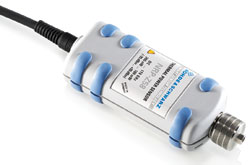
With the new R&S NRP-Z58 thermal power sensor, these problems are solved. A single 1 mm coaxial connector (male) makes it possible to cover the entire frequency range from DC to 110 GHz without interruption. The power measurement range extends from 0.3 µW (–35 dBm) to 100 mW (+20 dBm), thus covering the entire range to be measured. The new power sensor is light and easy to use, it can be operated directly from a PC via a USB interface and it offers additional features, including high measurement speed, excellent linearity, full traceability to renowned national metrology institutes and a means of internal verification option.
Not only is the R&S NRP-Z58 a good choice for power measurements on 1 mm coaxial ports, it can also replace waveguide power sensors in many other applications. The influence of any necessary adapters can be corrected at the sensor by numerically embedding the adapter’s S-parameters.
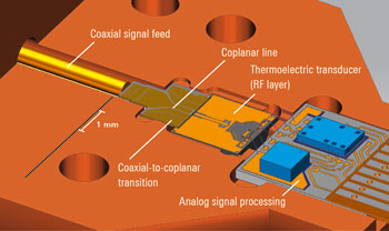
Figure 2 RF front-end with coaxial-to-coplanar transition.
Family Resemblance
The R&S NRP-Z58 110 GHz power sensor is part of the R&S NRP family of products and it incorporates the main features of the family. At the core of the new power sensor is the indirectly heated thermoelectric transducer – a Rohde & Schwarz development that combines very good impedance matching values with a high dynamic range and a response time of only a few milliseconds (see Figure 1).
The connection to the RF front-end is via a patent-pending wideband transition that converts the radially symmetric field of the incident wave to the field distribution of the coplanar transducer input, while at the same time providing excellent thermal isolation, as shown in Figure 2. These and other thermal design measures ensure that the zero drift remains negligible, even with ambient temperature changes or when screwing on the sensor.
Virtually no drift is expected under constant ambient conditions, because the architecture of the signal processing chain ensures that the 1/f measurement noise is suppressed. This is why the zeroing performed at the factory is sufficient in many cases. In addition, the R&S NRP-Z58 does without the internal zeroing function; as it would cause long, asynchronous interruptions in the measurement without providing any advantages.
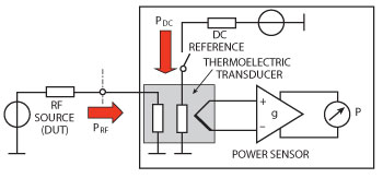
Figure 3 Circuitry for internal verification with DC.
DC Reference Circuit
To verify the thermoelectric transducer and the connected analog signal processing chain, the R&S NRP-Z58 power sensor has a DC reference circuit, shown in Figure 3, that makes calibration to an external 50 MHz reference source unnecessary. During calibration, the power sensor can remain connected to the DUT for as long as the DUT supplies a sufficiently stable signal. With a reproducibility in the range of 10–4, verification via the integrated DC reference circuit far exceeds an external calibration with an RF signal.
The more than 226 frequencies calibrated at the factory are fully traceable to the Physikalisch-Technische Bundesanstalt (PTB) national metrology institutes in Germany and the National Institute of Standards and Technology (NIST) in the United States.
In addition, Rohde & Schwarz makes use of a recently introduced microcalorimeter from the PTB that covers the entire W-Band. In this range, the calibration uncertainties of the new power sensor are 6 to 7 percent (calculated using GUM with a coverage factor of two).
Linearity
A high priority during development of the power sensor was to ensure a high degree of linearity for the power display, because this attribute is important for relative measurements. These include scalar attenuation, amplification and reflection measurements, as well as indirect power measurements using directional couplers, etc.
The absolute reference for indirect power measurements is normally obtained by means of a system calibration at a single level. With a linear uncertainty of maximally 0.23 percent (0.01 dB), the R&S NRP-Z58 is comparable to conventional, thermistor-based power sensors that use DC substitution to ensure high linearity. In the R&S NRP-Z58, the DC substitution was omitted in favor of measurement speed. Instead, a numeric linearity correction is used. This linearity correction is based on a calibration of the thermoelectric transducer with DC voltages performed at the factory, and it can remain unchanged for the life of the sensor.
Although the attainable measurement speed is comparable to that of state-of-the-art thermoelectric power sensors, it can vary significantly depending on the application. If the only goal is to record as many readings as possible within a given time span, the buffered mode can be used to record more than 300 readings per second. The aperture for a measurement point can be set very precisely to the millisecond, and the measurement can be either triggered or run continuously. Even if every reading is output separately instead of being buffered, about 250 triggered test results per second are still possible.
Averaging Factors
Of course, the rate of measurement will be slower when measuring low power values when it becomes necessary to average multiple test results in order to obtain a stable reading. However, the R&S NRP-Z58 can use averaging factors that are lower than those required by other W-Band products because its inherent noise is significantly lower. As a result, the settling times are more than ten times shorter than previously obtained, which means that even levels in the range of –10 dBm can be measured virtually without delay, while maintaining a satisfactory degree of stability.
The 1 mm connector on the R&S NRP-Z58 is essential for the impedance matching, reproducibility and stability of the new product. The coupling nut on the connector is fitted with ball bearings, which make it possible to hand-tighten the power sensor so precisely that there is no need for a torque wrench. The reduced friction also prevents the outer conductor from rotating when the coupling nut is tightened, thereby reducing wear and tear on the connector.
Rohde & Schwarz,
Munich, Germany
+49 89 4129 12345,
www.rohde-schwarz.com/ad/nrp/mwj