
RFID tags are often used in supply chain management and storage of a wide range of goods. In many cases, it is necessary to control environmental conditions because many products are sensitive to low or elevated temperature. Currently, this is carried out mostly with the use of indicators or expensive and complicated sensors. The latter contains electronic components, which make them inflexible. Indicators exhibit durability to bending but cannot be read wirelessly. As a result, they have to be placed outside a package and can be destroyed. A screen printed RFID-enabled temperature sensor, both flexible and wirelessly read, was developed and tested. It was fabricated with silver paste on a foil or paper. This sensor works in the UHF frequency range and provides a maximum read distance of 80 cm. Its properties were investigated with regard to the materials used, as well as environment and storage temperature.
Radio Frequency Identification (RFID) is one of the most popular automatic identification systems. It is often used in supply chain management and logistics.1,2 Many types of goods, such as dairy products or medicines, are susceptible to the influence of elevated temperature. Therefore, it is required to control their transportation or storage conditions. Otherwise, it can lead to their deterioration or even loss.
Nowadays, the temperature in a product environment is measured by various techniques. Semi-passive RFID systems are one of them. Their main component is a temperature logger, which records the temperature level and sends it to a reader. However, this device contains a battery that limits its lifetime and makes its unit cost higher, compared to RFID tags manufactured with printing techniques, such as inkjet,3,4 screen printing5,6 or photogravure.7
The temperature is also controlled with indicators, which have a much lower unit cost than loggers. Their color changes when the temperature increases.8 Their main disadvantage is the optical method to identify their state. It is inconvenient and makes the temperature control efficiency lower.
Currently, more and more studies are focused on RFID-enabled sensors, consisting of an antenna, a chip and an active element. These devices can be read wirelessly, so it is possible to place them inside a package to avoid their damage. Yao et al.9 described a low power temperature sensor with excellent power supply variation rejection ability for RFID tags. Other investigations were performed by Shenghua et al.10 and by Zhang et al.11 A temperature sensor integrated with a low power RFID tag chip was manufactured with 0.18 µm standard CMOS technology.
Other studies were presented by Guerin et al.12 and by Yang et al.13 A platinum-deposited based wireless temperature sensor was described by Guerin et al. based on a resistance change with temperature variations, which was combined with the frequency of a backscattering modulated signal. Yang et al. fabricated a wireless sensor transmitter, produced by an inkjet printing technique. It was a register, fitted with a temperature sensor and other electronic components, like quartz oscillator or battery. Thus, it was not flexible.
In this article, an RFID-enabled temperature sensor, manufactured on flexible substrates with screen printing techniques, is described. A UHF antenna was designed with the FEKO Suite and screen printed with a silver paste. A chip was assembled with a conductive adhesive and encapsulated with a fast flow underfill to increase its mechanical durability. An active element was printed with three types of silver pastes. The properties of the prepared temperature sensors were examined by reaction time measurements, depending on a substrate material and testing temperature level. In addition, their lifetime and read distance were estimated.
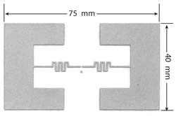
Figure 1 UHF antenna designed in this study.
Experimental
The UHF antenna, shown in Figure 1 and used in the RFID-enabled sensor, was designed with the simulation software FEKO Suite. Its return loss was taken into consideration. In the simulation, it was assumed that the antenna was made from silver on a foil (dielectric permittivity of 2.9, dissipation factor of 0.005 and thickness of 125 µm).
Then the simulated antenna was manufactured using a screen printing technique with a polyester mesh screen 68T. A polyethylene naphthalate (PEN) foil (Teonex Q51, from DuPont Teijin Films) and a photo paper (Everyday 180 g/m2, from Emtec) were used as substrate materials. The EL/Ag paste used for the antenna printing contained 70 percent weight silver flakes dispersed in a conductive polymer PEDOT:PSS in the form of an EL-P3040 paste (Agfa Gavaert). After the screen printing process, the antennas were cured at 120°C for 15 minutes.
In the next step, an RFID chip in an SOT-323 package (Alien Technology) was attached to the antenna using a conductive adhesive Ecolit 3654 (Panacol), which was cured at 120°C for 10 minutes Then these components were encapsulated with a fast flow underfill e1216 (Emerson & Cuming) and cured at 130°C for 10 minutes. Their shear force before and after encapsulation was measured with a Force Testing System Mecmesin i-1.
Finally, an active element of the RFID-enabled sensor was printed with the EL/Ag paste, a commercial silver paste PF-050 (OEM Electronics) and an SF paste. The last one consisted of 66 percent weight of silver flakes dispersed in a poly(methyl methacrylate)-poly(butyl methacrylate) (PMMA-PBMA) dissolved in butyl carbitol acetate with a concentration of 10 percent weight. After the printing process, all the pastes were cured at 120°C for 15 minutes.
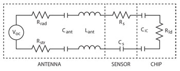
Figure 2 Schematic of the temperature sensor.
The reaction time and long term stability of the active element of the fabricated RFID-enabled sensor were measured. The first parameter was defined as the time period to decrease the resistance of an active element below 100 Ω. It was estimated by continuous resistance measurements, during exposure to elevated temperatures (80° to 140°C). The stability of the active element resistance was evaluated by its measurements after storage in ambient conditions and in a refrigerator (-4°C) or in a freezer (-12°C). The read distance of an elaborated sensor was measured using an RFID reader tt8300 t+t netcom.
Sensor Conception
The sensor was constructed, based on the idea that under elevated temperature, its resistance will change rapidly. The resistance decrease is permanent so it was not possible to increase it again. An electrical schematic of the designed sensor is shown in Figure 2.
The power wave reflection coefficient S11 can be expressed by the following equation:15
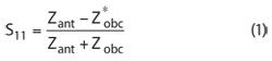
where Zobc is the load impedance.
The antenna impedance Zant is equal to:
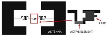
Figure 3 Schematic diagram of the RFID-enabled temperature sensor.
Rrad is the radiation resistance, Rstr is the antenna loss resistance and XL and XC are the inductive and capacitive reactances of the antenna.
In the designed temperature sensor, a change in the antenna resistance Ra took place:
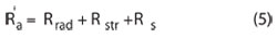
Along with an increase in the resistance RS, the antenna loss resistance (Rstr + Rs) increased. It resulted in a decrease of the power of the backscattering signal received by an RFID reader. When RS decreases rapidly, most of the signal transmitted to a reader was interpreted as an exposure of a sensor to elevated temperature.
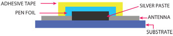
Figure 4 Cross-section of the sensor.
The schematic diagram of a fabricated RFID-enabled temperature sensor is shown in Figure 3. The main part of the sensor is an active element, a layer of silver paste placed in a gap in an antenna circuit (see Figure 4). The two layers (PEN foil and an adhesive tape) on the top of the sensor were used to protect the active element against external conditions, such as humidity or dust. They also prevent against rapid evaporation of the solvent contained in the silver paste.
Results and Discussion
Antenna Simulation
The UHF antenna was simulated by the FEKO Suite software in the frequency range of 0.5 to 1.5 GHz (see Figure 5). Its return loss was taken into consideration. The basic resonant frequency of the designed antenna was 876 MHz for the load impedance of Z = (32 - j228) Ω. The bandwidth of the antenna was greater than 200 MHz, which fully covers the UHF frequency band 860 to 960 MHz.
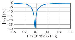
Figure 5 Simulated S11 vs. frequency for the load impedance Z = (32 - j228) Ω.
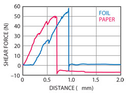
Figure 6 Shear force of the encapsulated chips assembled on foil and paper.
Chip Assembly
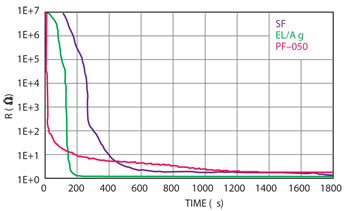
Figure 7 Resistance of an active layer depending on exposure time to 120°C.
The mechanical durability of the assembled RFID chips was tested by shear force measurements.
For all non-encapsulated chips, regardless of the substrate used (foil or paper), the measured
shear force was below 1 N. Its value was insufficient for practical applications and therefore the
chips were encapsulated. It resulted in an increase of shear force up to 50 ± 7 N for the chips
assembled on paper and up to 58 ± 11 N for the chip mounted on foil (see Figure 6).
The higher value of the shear force for encapsulated chips resulted from an increase of the
bonding force between them and the substrate, resulting from a larger bonding surface.
A type of substrate seemed to have an impact on a mechanical durability of the assembled
chips. The surface of the polymer coated paper cracked during the shear test and this could
contribute to a lower value of shear force in comparison to foil.
Sensor Properties
A basic parameter, describing properties of the investigated sensor, was the reaction time. As
mentioned in the experimental section, the reaction time was defined as a period in which the
resistance of an active element decreased below 100 Ω. It was evaluated for the temperature of 80°, 100°, 120° and 140°C. Under the influence of a temperature increase, a paste started to polymerize as a result of a solvent evaporation. Thus, the resistance of an active layer decreased rapidly (see Figure 7).
The measured reaction time for active layers printed with the pastes: PF-050, EL/Ag and SF was equal to 30 ± 10 s, 135 ± 5 s, 315 ± 15 s, respectively. Its value depended strongly on the type of paste used, particularly on the solvent type. In the material (EL/Ag), a commercial paste (EL-P3040) was utilized as a polymer carrier. According to the manufacturer recommendation,14 its curing conditions should be 120°C for only 3 minutes. In the case of the paste (SF) the curing temperature of the printed layer was also 120°C, but the time was 15 minutes. The five times longer curing time could cause the solvent to evaporate from this material much slower and in consequence, the SF sensor exhibited longer reaction time.
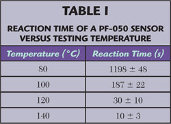
The reaction time depended also on the testing temperature (see Table 1). At higher temperatures, polymerization occurred faster because of faster solvent evaporation. This resulted in shorter reaction time. Based on the achieved results, a model describing the reaction time against temperature is proposed. It can be expressed as:
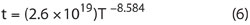
where t is the reaction time and T is the temperature.
In the case of a sensor printed on paper, it was not possible to evaluate its properties. Solvents were absorbed by the substrate immediately after the printing process and, in consequence, the resistance of the active element decreased rapidly.
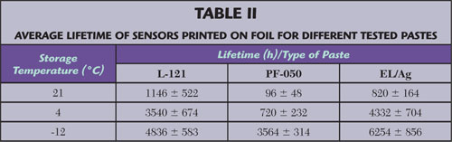
The second estimated parameter of sensors was their lifetime. It was evaluated depending on the storage temperature. The results shown in Table 2 show that the lifetime, defined as a period in which the resistance of an active layer decreased below 100 Ω, increased when samples were stored in a colder environment. This was a result of a slower solvent evaporation.
The last tested parameter, which characterized the developed sensor, was the read distance. Its maximum value was 80 cm, placing the sensor inside a package for practical applications.
Conclusion
In this article, the measurement results of reaction time and lifetime for a screen printed RFID-enabled sensor fabricated on flexible substrates are presented. It is stated that the measured reaction time depended on the type of paste used and testing temperature. Its value was from 10 to 1198 s, when the testing temperature increased from 80° to 140°C. At 120°C, the reaction time was equal to 30 ± 10 s, 135 ± 5 s, 315 ± 15 s for the pastes PF-050, EL/Ag and SF. The maximum read distance of the developed sensor was 80 cm. The sensor was functional for at least for 3564 h (more than 148 days), which made them applicable in practical applications.
References
- K. Finkenzeller, RFID Handbook, 2nd Edition, John Wiley & Sons, New York, NY, 2003.
- K. Janeczek et al., “Thermal Characterization of Screen Printed Conductive Pastes for RFID Antennas,” Material Science and Engineering: B, 2012 (available online).
- K. Futera et al., “Low Cost Inkjet Printing System for Organic Electronic Applications,” Mechatronics, Part VII, 2012, pp. 713-721.
- T. Wei et al., “Preparation of a Carbon Nanotube Film by Ink-jet Printing,” Carbon, Vol. 45, No. 13, November 2007, pp. 2692-2716.
- M. Jakubowska et al., “Printed Transparent Electrodes Containing Carbon Nanotubes for Elastic Circuits Applications with Enhanced Electrical Durability Under Severe Conditions,” Material Science and Engineering: B, Vol. 176, No. 4, March 2011, pp. 358-362.
- K. Janeczek et al., “Investigation of UHF Antennas Printed with Polymer Pastes on Flexible Substrates,” IET Microwaves, Antennas & Propagation(accepted for publication).
- M. Pudas et al., “Gravure Printing of Conductive Particulate Polymer Inks on Flexible Substrates,” Progress in Organic Coatings, Vol. 54, No. 4, December 2005, pp. 310-316.
- Thermax Encapsulated Indicators, www.tmchallcrest.com/industrial php?medical_product=68&sublvl_id=5&subcat_id=14.
- L. Yao et al., “A Low Power Temperature Sensor for Passive RFID Tag,” Proceedings of the 12th International Symposium on Integrated Circuits, 2009, pp. 699-702.
- Z. Shenghua and W. Nanjian, “A Novel Ultra Low Power Temperature Sensor for UHF RFID Tag Chip,” 2007 IEEE Asian Solid-State Circuits Conference Digest, pp. 464-467.
- Qi Zhang et al., “A Novel RFID Tag Chip with Temperature Sensor in Standard CMOS Process,” 2010 IEEE International Symposium on Circuits and Systems Proceedings(ISCAS), pp. 1109-1112.
- M. Guerin et al., “A Temperature and Gas Sensor Integrated on a 915 MHz RFID UHF Tag,” 2010 IEEE International Conference on Wireless Information Technology and Systems Proceedings(ICWITS), pp. 1-4.
- L. Yang et al., “Wearable RFID-enabled Sensor Nodes for Biomedical Applications,” 58th Electronic Components and Technology Conference Digest, 2008, pp. 2156-2159.
- Datasheet of the paste EL-P3040.
- P.V. Nikitin et al., “Power Reflection Coefficient Analysis for Complex Impedances in RFID Tag Design,” IEEE Transactions on Microwave Theory and Techniques, Vol. 53, No. 9, September 2005, pp. 2721-2725.