
Radar altimeters (or radio altimeters) have been used on aircraft since the mid-1950s. Together with barometric pressure altimeters and more recently GPS and radio timing positioning systems, radar altimeters are a critical part of modern aircraft avionics that increase flight safety, reliability and capability.
Radar altimeters are primarily used during flight at altitudes below 5000 feet and are key tools for critical maneuvers, including take-off and landing approaches. Low flying aircraft, like helicopters and Unmanned Aerial Vehicles (UAV), rely on radar altimeters (RA) for nearly all operations. UAV and some manned aircraft may be operated remotely, consequently the success of the mission and safety of the passengers and crew are dependent on the accuracy and performance of the RA. Verifying performance and calibrating RAs quickly and reliably take place at RA manufacturing sites, calibration centers and flight line avionics depots. The capability of the necessary test equipment varies based on the site. For example, during RA product development and qualification, detailed testing over a variety of environmental and performance conditions are necessary, whereas flight line testing may only include verification test at a few altitudes. Calibration requires NIST-traceable standards testing to ensure accuracy. Depending upon the test site and requirements, a variety of test tools may be selected, based on cost, capability, ease of use and reliability. Eastern OptX has produced equipment for use in each of these applications and has optimized the performance to meet the testing needs with rugged and competitive systems.
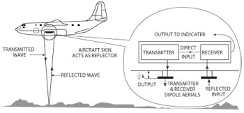
Figure 1 The altitude is given by A = c |∆f|/(2(df/dt)) (Dick Barrett, Radar Theory, 2000-2002).
Historically, RAs have used a Frequency Modulated Continuous Wave (FMCW) scheme because it is capable of achieving the low altitude accuracy required with a simple and reliable system. Figure 1 shows the FMCW system. An RF signal (typically 4.3 GHz) is modulated with a swept IF signal, typically from 400 to 440 MHz. The rate of change of the sweep is typically 0.2 MHz per second. That signal is then transmitted from an antenna mounted on the underside of the aircraft, typically in the forward section and radiated toward the earth. The signal reflected from the earth is then detected using a separate receive antenna located some distance from the transmit antenna. Care must be taken to provide isolation between the two antennae to avoid stray paths that might be confused with the aircraft-to-earth path, particularly at low altitudes. The received signal is mixed with a sample of the broadcast signal and the resulting frequency difference (Δf) is directly proportional to the round trip distance between the aircraft and the earth. The FM span and slew rate are selected to optimize distance measurement accuracy at near-earth altitudes.
There are several methods used to test RAs. One of the most compact, accurate and reliable is the Fiber Optic Delay Line (FODL) method. The FODL method exploits the small size, lightweight, low loss and low drift properties of optical fiber transmission lines to create a system that replicates the channel properties that RAs face in actual operation. Figure 2 shows a typical FODL used for RA testing.
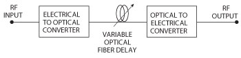
Figure 2 Typical fiber optic delay line.
The RF signal transmitted from the altimeter is used to modulate a broadband optical laser and the output of the laser passes through a variable delay line. The delay line distance may be adjusted to match a desired altitude and the delay output is converted back into an electrical signal using an optical detector. The RF output is then used as the input to the altimeter receiver. The optical delay provides a precise altitude with accuracy better than 0.1 percent and offers steady, repeatable performance.
EA-6061 Altimeter Test Set
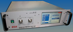
Eastern OptX has introduced the EA-6061 altimeter test set that is targeted at RA calibration and system design. The EA-6061 is an automated system with variable delay and calibrated propagation loss. Operating with any altimeter transmission protocol, it is easy to use from either the front panel touch screen or via remote commands. The GUI provides access to built-in self-test and both manual and coupled operation with user-selectable aircraft cable compensation. Figure 3 shows the EA-6061 altimeter test set.
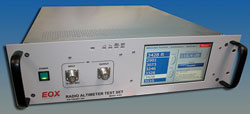
Figure 3 The EA-6061 altimeter test set.
EA-6061 system details:
- Altitude: Variable, 0 to 6350 ft in 50 ft steps
- Propagation loss: Locked to altitude setting or user controlled
- Aircraft cable compensation: Four user-defined settings
- Calibration: Built-in self calibration with short and open I/O options
- Sample ports: 10 and 20 dB taps
- LCD front panel touch screen and Ethernet remote control
- Programmable ascent and descent scenario generator
EA-6071 Altimeter Test Set
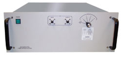
Figure 4 The EA-6071 altimeter test set.
For depot level or production testing, Eastern OptX introduces the EA-6071. This system provides an economical easy-to-operate system that is small, lightweight and offers a battery power option for operation on the flight line. The convenient user interface makes operator training quick and reduces the chance of set-up errors during RA testing. This is a great tool for quick RA performance verification and, with better than 1 percent accuracy, may be used to calibrate the RAs well. Annual system verification is recommended, however calibration is not required. Figure 4 shows the EA-6071 altimeter test set.
EA-6071 system details:
- Altitude: Fixed, 0, 250, 500 and 1000 ft
- Propagation loss: Locked to altitude setting
- Aircraft cable compensation: Three user-defined settings
- Front panel rotary switch control
- External delay option
In addition to operation with CWFM systems, FODL devices will operate with any in-band signal regardless of the modulation type, encryption, frequency agile, or spread spectrum modes. This advantage also allows the system to be used for altimeter development, since it accepts any and all signal variations as long as they are in-band. The typical bandwidth of fiber optic systems varies between 0.1 to 18 GHz. This feature is especially useful with modern Low Probability of Intercept (LPI) radar altimeters. LPI systems are designed to minimize signal detection and subsequent source and target location. Primarily used on military aircraft, LPI RAs reduce source detection using the following methods:
- Frequency-hopping (spread spectrum) RF signal to reduce RF energy at a particular frequency and lower the signal power to near background noise levels
- Pseudo-random hopping algorithms
- Encrypted transmission data
Transmission power management to minimize signal level to the minimum required for altimeter detection
Both the EA-6061 and EA-6071 provide testing for FMCW and LPI RAs, without any special modification. As the use of LPI RAs increases, particularly on UAVs, there will be additional need for fast calibration and verification of performance using FODL devices. FODLs may also be incorporated into aircraft for onboard RA self-test and alignment. Additional FODL features, including multipath and Doppler shift replication, help designers test existing hardware as well as next generation altimeter designs without the need for costly and untried test systems.
Eastern OptX,
Moorestown, NJ
(877) 870-6789,
www.eastern-optx.com