Unlike other numerical simulation areas like stress or thermal analysis, high frequency computational electromagnetics is an evolving science. Experts still argue about the fastest and most elegant approaches to solving problems and no single method has emerged as an outright winner. To make headway, development teams have to invest time and money in pure research projects with all the associated risk and potential reward that this brings. With a trend towards larger and ever more complex designs, the potential reward for the end-user is the ability to solve previously intractable problems quickly and accurately.
Since CST started almost 15 years ago, the ultimate aim of the company’s research approach has been to provide a commercial tool with very strong solvers while also considering other areas of interest to the user — easy data entry and flow from other CAD/EDA tools and clear and intelligible post-processing. The new 2006B release of CST MICROWAVE STUDIO® (CST MWS) goes a long way towards providing this “complete technology.” Virtual prototyping using the most appropriate solvers and meshes is now a reality with the added benefit of multiple solvers offering cross-verification of results. Confidence in 3D computational electromagnetics has never been higher.
Workflow Integration
In a competitive workplace, modern engineers need to have access to an excellent software toolbox to help them achieve their daily tasks. In the microwave, RF and high speed world, active and passive circuit simulation tools are essential so that slow and tedious “cut and try” methods can be eradicated. CST has always focused on being the specialist in passive 3D EM field simulation, but recent partnerships with best-in-class active simulation tools as provided by Agilent and AWR have allowed true co-simulation and co-optimization of a complete active/passive design. Examples include a transistor network powering an antenna where both the active circuit components and the antenna components can be parameterized and optimized.

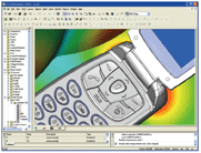
A starting point for many passive simulations is the requirement to import a legacy or previous generation design available in either a mechanical CAD tool like Pro/E or a layout tool like Cadence Allegro. The latest Cadence interface is shown in Figure 1, where bondwire properties can now be included. Most engineers would rather not rebuild the model in a new interface no matter how good it is. However, the problem has always been that the electomagnetic simulation requirements are tough compared to the mechanical requirements.
Version 2006B of CST MWS takes a large step forward in this area by introducing a method called Fast Perfect Boundary Approximation (FPBA). PBA itself was a breakthrough back in 1998 when the first version of CST MWS was launched. It allowed a time domain technique to represent curves and inclines very accurately by applying an integral approach to solving Maxwell’s equations. FPBA takes another major step forward, by enabling the fast and robust discretization of imported models, including those corrupt geometrical descriptions. This removes the tedious stage of “healing” a model. The title picture shows a complex cell phone simulated in the software.
Flexible Subgridding in the Time Domain
A vastly challenging blue-sky research project, subgridding has tested the brightest minds, but the release is now here and it provides an exciting breakthrough in time domain technology. Flexible subgridding combines CST’s existing PBA and TST (thin sheet technology) with true general conforming behavior.
While there are commercial products available that subgrid rectangular volumes, they lack flexible and conforming behavior and are limited to “staircase” representation of objects. The breakthrough in CST MWS comes with the combination of many technologies to make a truly adaptive and numerically stable scheme without sacrificing existing benefits.

Figure 2 illustrates where the scheme is most applicable — models where there are large differences in scale. In this case a human head and the small helix of a cell phone antenna where time domain’s traditional uniform grid requires extension of the mesh cells to the boundary of the problem. The new method allows a “focus” of mesh cells around the small helix feature with a progression to large cells away from the feature where there is smaller spatial field variation. Mesh cells can be split in either x, y, or z directions or all three depending on the structure. For example, a planar structure would require a split in only one plane to correctly capture the metal edge behavior. In the illustrated example, the reduction in cell count is huge at over 10:1 with an even larger ratio reduction in overall run time.
Why Include Other Solvers?

The history of CST MICROWAVE STUDIO® is based in the time domain where many years of research and development and constant updates have produced the world’s most successful tool in its class. However, despite having the ability to solve a vast array of problems, in particular large or broadband devices, other techniques have shown advantages for certain classes of problem. A frequency domain method based on tetrahedral meshing with adaptive meshing and fast-frequency sweep was introduced in version 5.1 primarily to focus on the subset of problems where the technique excelled. These included narrow band or electrically smaller devices such as a high Q filter, a SiP with a coil over a substrate or a phased-array antenna (see Figure 3). One overriding goal of its introduction was to ensure that the interface was completely common to the time domain solver, so that the user simply had to press “T” or “F” to start the appropriate solver.

2006B completes the set of features required for a world-class frequency domain solver, including both direct or iterative techniques, first- and second-order approaches, advanced Delaunay volume meshing, slanted ports, plane wave excitation, multi-frequency mesh adaption and Floquet boundaries for unit cell phased-array structures. Figure 4 shows a circulator example solved with slanted ports.
New Solver
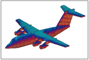
2006B introduces a brand new specialist full-wave solver for the solution of electrically very large structures where the structure is perhaps 10s or 100s of wavelength in size. Examples may include antenna interoperability studies or radar illumination of an aircraft. This Integral Equation solver uses the multi-level fast multi-pole method (MLFMM). A special approach to solving the method of moments (MoM) technique, including only having a surface mesh, the MLFMM solver has several key advantages. Traditional MoM solvers are great for simple metallic or wire type antennas where there is only a small surface to mesh and lots of free space. Large and complex devices become troublesome due to the coupling of every element required in the scheme leading to a large, dense matrix. Scaling for such problems is notoriously bad and they quickly become insoluble. The new method’s multi-level function reduces full coupling to within multiple small cubic volumes of the model. These are then coupled in a similar way to a larger volume and so on recursively until one volume remains. Scaling for numbers of cells is vastly improved at Nlog(N). This new specialist solver fits into the existing interface framework. Figure 5 shows an aircraft simulated with the new solver.

To round out the list of solvers available in 2006B, improvements have been made to the established eigenmode (E) solver including speed improvements and the ability to select a frequency window for modes, rather than calculating all modes from 0 Hz. The Fast Resonant (R) solver continues to provide lightning quick S parameter calculations of high Q filters.
The general-purpose time and frequency domain solvers will suit the vast majority of applications, but the three specialist solvers will help the engineer solve niche problems quickly and accurately.
Modeler and Other Improvements
Many improvements will benefit the user in version 2006B. To allow for the trend of ever more complex models, the front-end modeler includes a feature reduction on movement to guarantee 15 frames per second. Hover Selection allows easy selection of parts and hidden parts (see Figure 6) in the view or the navigation tree. Smart View rotation automatically centers rotation at the mouse. In post-processing, Adaptive Vector Plots plots an appropriate number of vectors according to the zoom level.

Switching between low and high frequency simulation is now a one-button operation and the menus and icons automatically reconfigure. Coupling of magnetostatic and high frequency solvers is complete, so that biased ferrites can be solved in devices such as circulators. Coupled thermal simulation is also available.
CST DESIGN STUDIO,™ an entry-level circuit simulation alternative to ADS from Agilent or Microwave Office from AWR, now has a time domain solver, allowing eye diagram creation, for example.
Conclusion
2006B may sound like an intermediate release; however, this must be one of the most understated names in commercial computational electromagnetics. CST has recognized that the world of RF, microwave and high speed design is rapidly evolving and moving toward ever-greater complexity. The combination of world-class solvers and a leading-edge interface has also evolved to meet that challenge head-on. With the multiple benefits of faster throughput and lowered design cost and risk, engineers and their managers may want to look at this release more closely. A no-obligation 30-day trial can be arranged by contacting the company via e-mail at info@us.cst.com.
CST of America,
Wellesley Hills, MA
(781) 416-2782,
www.cst.com.
