
 The ADF4159 from Analog Devices is a 13 GHz PLL synthesizer that achieves a phase detector operating frequency of 110 MHz while simultaneously consuming less than 100 mW of power. The device contains a 25-bit fixed modulus as well as on-chip functionality to generate highly linear ramp profiles, making it an ideal solution for frequency-modulated continuous-wave (FMCW) radar applications, including automotive radar systems. The ADF4159 is also ideal for microwave point-to-point (PtP) systems, communications infrastructure, instrumentation and test equipment.
ADI’s ADF4159 fractional-N PLL synthesizer consists of a low-noise digital phase frequency detector (PFD), precision charge pump and a programmable reference divider. It can be used to implement frequency shift keying (FSK) and phase shift keying (PSK) modulation. There are also a number of frequency sweep modes available that generate various waveforms, such as sawtooth and triangular waveforms. The functional block diagram of the ADF4159 is shown in Figure 1.
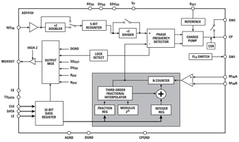
Figure 1 ADF4159 functional block diagram.
Applications
ADI’s high-performance ADF4159 PLL features industry-leading phase noise performance of −223 dBc/Hz and 1/f noise performance of −120 dBc/Hz. The very high maximum PFD frequency allows for very good in-band phase noise while it also allows for very wide loop bandwidths if extremely fast settling time is required.
The ADF4159 supports a 25-bit fixed modulus which allows for very fine resolution. The minimum channel spacing is calculated by dividing the PFD frequency by 225, so for a 100 MHz PFD frequency, the minimum channel spacing is 2.98 Hz. Lower minimum channel spacing can be achieved by reducing the PFD frequency using the internal reference divider. The overall N divider value is calculated from the programmed INT and FRAC values.
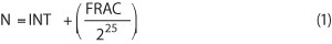
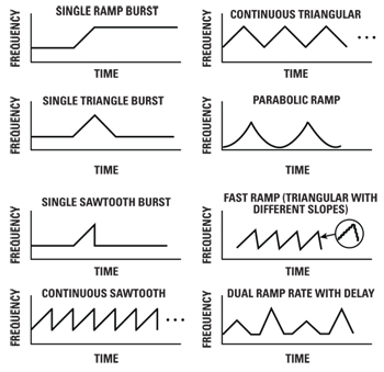
Figure 2 Some of the frequency ramps that the ADF4159 can generate.
The ADF4159 is powered by a 2.7 to 3.3 V analog power supply and a 1.8 V digital power supply. The typical current drawn by the part is 33 mA.
Ramp Generation
ADI’s ADF4159 PLL can generate a variety of frequency sweeps or ramps. The ADF4159 is initially programmed once and will continue to output the changing frequency without the need to re-program the part for each frequency. The frequency deviation of each step, the number of steps and the time each step takes can be individually controlled to optimize system performance. The ramp can be clocked by the internal clock or by an external pin for synchronous control.
Ramps can range anywhere from hundreds of megahertz in tens of microseconds, to tens of hertz in minutes. Some of the frequency ramps that the ADF4159 generates can be found in Figure 2. Time delays can be added to any of the ramps, either at the start of the ramp or between ramp cycles. FSK, PSK and sawtooth waveforms with FSK superimposed onto the signal can be implemented on the ADF4159 by toggling the logic level on an external pin.
In addition, the ADF4159 is supported by Analog Devices’ ADIsimPLL™ design tool, which simulates and optimizes ramping profiles. This software is a free download available at www.analog.com/adisimpll.
ADF4159 in FMCW Radar
A block diagram of an FMCW radar is shown in Figure 3. The sweeping frequency is transmitted from the Tx antenna, bounces off the target (for example, a vehicle in the next lane) and is received by the Rx antennas. The received signal can then be compared to the transmitted signal to establish the distance to the target. The distance to the target is calculated as follows:
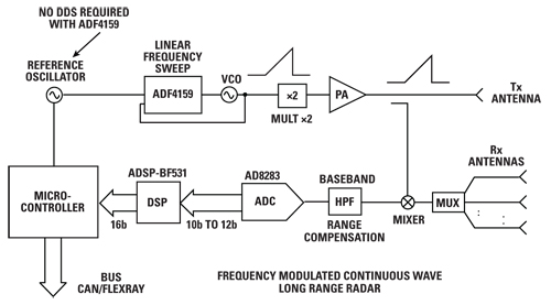
Figure 3 FMCW radar block diagram.
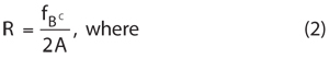
- R = Distance to target (m)
- fB = Beat frequency (Hz)
- c = Speed of light (3 × 10⁸ m/s)
- A = Sweep rate of modulating waveform (Hz/s)
For example, a FMCW radar is operating by sweeping frequency from 24 to 24.1 GHz in 5 ms. It is modulated by a sawtooth signal. That gives A = 20 GHz/s. The measured difference between the transmitted and received signal is fB = 1.3 kHz. This means that the target is 9.75 m away.
For a 24 GHz radar system, the ADF4159 can be locked to the divide-by-2 output of a 24 GHz VCO. Alternatively, the VCO can operate around 12 GHz and its output frequency multiplied by 2 to generate the Tx signal. Signals for 77 to 79 GHz radar systems can be generated in a similar manner.
To generate a system where the output sawtooth ramps from 24 to 24.1 GHz in 128 µs, the ADF4159 needs to be programmed to output a ramp from 12 to 12.05 GHz in 128 µs. If the system requires 256 frequency steps per ramp, the frequency deviation of each step is determined by dividing the total ramp frequency, 50 MHz, by the number of steps, 256. This results in a frequency deviation of 195.3125 kHz per step. Alternatively, if the frequency deviation per step is fixed, then the calculation can be reversed to find the number of steps, for example, 50 MHz divided by 200 kHz is 250 steps. The ADF4159 can be programmed to output any amount from 1 step to over 1,000,000 steps.
To generate the ramp in 128 µs, with 256 steps, each step will take 0.5 µs. The 0.5 µs is generated by programming two timers on the ADF4159. To achieve 0.5 µs per step, the loop filter bandwidth (LBW) must be wide enough to allow the loop to lock quickly enough. On the ADF4159, with its high maximum PFD frequency, this is easily achievable.
The maximum PFD frequency of the ADF4159 is 110 MHz. In order to maintain loop stability, the LBW cannot be greater than 1/10 of the PFD frequency. The ADF4159 is a fractional-N PLL, so care should be taken to attenuate sigma delta modulator (SDM) noise. Ideally, to suppress the SDM noise to acceptable levels, the LBW cannot be greater than 1/100 of the PFD frequency. Using ADIsimPLL, the optimum loop filter can be designed and simulated to ensure sufficient lock time and noise attenuation.
Analog Devices
Norwood, MA
www.analog.com