
The demand for small, compact, low cost, high performance filters, diplexers and multiplexers using MIC technologies has increased along with advances in microwave systems. Capacitive-loaded interdigital filters are compact in size, have sharp roll factor, excellent broad stopband performance and are easy to fabricate. A filter with tapped-line is even more compact, and offers space and cost-saving advantage over a conventional filter. The tapped-line filter is also beneficial in situations where coupling at the end section becomes practically unrealizable.1,2 This type of filter is easy to interface with other circuit components. This article presents a capacitive-loaded interdigital bandpass filter with tapped input/output on suspended substrate stripline in printed circuit form.
Tapped-line interdigital filters have been described by several authors.1–4 Caspi and Adelman2 suggested an open-wire line equivalent circuit based on work by Crystal,3 and derived an analytical expression valid up to an octave bandwidth for interdigital filters. The interdigital filter structure consists of resonators formed by coupled-line elements ![]() /4 long at the center frequency, with alternate ends of the coupled elements grounded, and opposite ends open-circuited. The coupled resonators can be made shorter than
/4 long at the center frequency, with alternate ends of the coupled elements grounded, and opposite ends open-circuited. The coupled resonators can be made shorter than ![]() /4 at mid-band providing loading capacitances are added at the open-circuited element ends.5 With a capacitive load at the open-circuited element ends, the filter becomes physically compact in the transverse direction. This loading manifests itself by shifting the second passband (that is the first spurious passband) to a higher frequency. The shorter the resonators at mid-band, the wider the separation between the first and second passband.
/4 at mid-band providing loading capacitances are added at the open-circuited element ends.5 With a capacitive load at the open-circuited element ends, the filter becomes physically compact in the transverse direction. This loading manifests itself by shifting the second passband (that is the first spurious passband) to a higher frequency. The shorter the resonators at mid-band, the wider the separation between the first and second passband.
The capacitive-loaded interdigital filter retains all the other advantages of the filter without loading. In addition, it offers relatively large spacing between coupled line resonators and provides relatively relaxed manufacturing tolerances. The attenuation slope and magnitude of the stopbands are enhanced by multiple-order poles at zero frequency and between the passband.
Design Approach
 | |||
| Fig. 1 Suspended substrate stripline. | |||
Design expressions for the tapped interdigital filter in terms of even and odd impedances4 along with the loading capacitance at the open end of the resonator of the combline filter2 are used for the initial design of a capacitive-loaded interdigital bandpass filter. The design begins with the selection of the admittance Ya of the resonator line, the center frequency and the electrical length ![]() o. The electrical length can be selected as desired (shorter than
o. The electrical length can be selected as desired (shorter than ![]() /4 ). The resonator impedance is normally selected for a high resonator Q factor, approximately 76
/4 ). The resonator impedance is normally selected for a high resonator Q factor, approximately 76![]()
![]() . In designing the capacitive-loaded interdigital filter, an equal width of the resonators is chosen, that is the width of a 76
. In designing the capacitive-loaded interdigital filter, an equal width of the resonators is chosen, that is the width of a 76![]() line on a suspended substrate stripline, as shown in Figure 1. Keeping the width of the resonators constant, the spacing between the resonators is varied to obtain the required coupling coefficients from the calculated even- and odd-mode impedance4 for the desired bandwidth. The use of equal width of the resonator strips simplifies the design and analysis of the filter.
line on a suspended substrate stripline, as shown in Figure 1. Keeping the width of the resonators constant, the spacing between the resonators is varied to obtain the required coupling coefficients from the calculated even- and odd-mode impedance4 for the desired bandwidth. The use of equal width of the resonator strips simplifies the design and analysis of the filter.
Tapping of the input and output 50![]() lines to the first and last resonators reflects an inductance at the end of the resonators, which can be compensated by either a lumped capacitance equal to Cs of the interdigital filter2 or by an extension in the length of the end resonators.1 The loading capacitance of the first and last resonators including the tapping effect becomes Cs + Cmid. The loading capacitance of the internal resonators, Cmid, can be calculated by
lines to the first and last resonators reflects an inductance at the end of the resonators, which can be compensated by either a lumped capacitance equal to Cs of the interdigital filter2 or by an extension in the length of the end resonators.1 The loading capacitance of the first and last resonators including the tapping effect becomes Cs + Cmid. The loading capacitance of the internal resonators, Cmid, can be calculated by

where
![]() o = electrical length of the resonator
o = electrical length of the resonator
![]() o = 2
o = 2![]() fo
fo
fo = center frequency of the filter
As the loading capacitance Cmid approaches zero (Cmid -> 0), the electrical length will approach 90° (![]() o ->
o -> ![]() /2). When the electrical length is 90°, the Cmid is zero and the capacitive-loaded interdigital bandpass filter becomes a standard interdigital bandpass filter.
/2). When the electrical length is 90°, the Cmid is zero and the capacitive-loaded interdigital bandpass filter becomes a standard interdigital bandpass filter.
After calculating the width and spacing corresponding to the even- and odd-mode impedances in suspended substrate stripline,6 the LINPAR software7 is used for calculating the [L], [C], [R] and [G] matrices per unit length. With the help of these matrices, the filter response is calculated theoretically by using the LINPAR software,8 which takes care of the nonadjacent coupling and composite effects of multiple quasi-TEM modes.
Realization
In the conventional method, capacitive-loaded interdigital filters have been realized using metal bar resonators5 in a TEM field configuration. In this article, the capacitive-loaded interdigital filter has been realized with a suspended substrate stripline, that is a quasi-TEM mode configuration. This change in the design medium improves the loss characteristics of the filter.
The conventional metal bar resonator can be visualized as an equivalent suspended substrate stripline resonator with its alternate ends grounded via a plated through hole (PTH). The loading capacitors are replaced by metal-insulator-metal (MIM) printed capacitors. It appears at first glance that the proposed quasi-planar circuit is simply a one-to-one replacement of the conventional metal bars circuit. But they differ by one major guided-wave property. Namely, the quasi-planar realization supports N zero-cutoff frequency quasi-TEM modes in addition to all possible excitation of other higher order modes.
The second critical issue in the realization of a quasi-planar circuit is the associated coupling between nonadjacent resonators, that is between the first and third resonator, and becomes a serious problem when the filter dimensions are made smaller. This coupling is quite important, having a significant effect on the filter response. The conventional design approach5 neglects these effects.
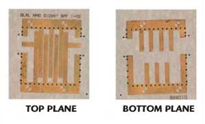
The third issue is related to the accurate printing of the MIM capacitors. On the opposite side of the coupled suspended substrate stripline (SSS) resonator, a toothed metallization pattern is printed well aligned under the corresponding resonators. The width of the metallization is taken equal to the width of the resonator and the length of the toothed metallization is calculated by

where
Cmid = lumped loaded capacitance of the open end of the resonator
W = width of the toothed metallization
d = the substrate thickness
![]() r = substrate relative dielectric constant
r = substrate relative dielectric constant
For realizing the actual metallization required for the capacitor, the fringing capacitance of the open-end resonator should be considered because it increases the total capacitance, which leads to a shift of the filter response to a lower frequency. The shift in center frequency of the filter response is corrected by a slight trimming of the toothed metallization on the back of the substrate.
In the realization, the tapping effect of the input/output is compensated by increasing the first and last resonator length by approximately 10 percent of the actual length of the resonator. A five percent increase is usually required in L band,1 and the other five percent is usually trimmed off during adjustment. The lengthening of the input and output resonators is required to compensate the effect of the physical tap-point and to obtain a correct length at the resonant frequency and experimentally correct the tap-point location. During each test, the input/output resonators are gradually trimmed off at the open end until the input and output VSWR have reached an optimum valve, resulting in equal ripple performance across the passband.
The input and output 50![]() transmission line is printed on the composite substrate stripline. A dielectric material 0.5 mm thick and with
transmission line is printed on the composite substrate stripline. A dielectric material 0.5 mm thick and with ![]() p = 2.2 is inserted beneath the substrate to reduce the width of the 50
p = 2.2 is inserted beneath the substrate to reduce the width of the 50![]() transmission line, which in turn reduces the width of the T-junction formed at the tapping position.
transmission line, which in turn reduces the width of the T-junction formed at the tapping position.
Performance Evaluation
 | |||
| Fig. 2 The 1.25 to 1.75 GHz filter. | |||
 | |||
| Fig. 3 Measured response of the 1.25 | |||
 | |||
| Fig. 4 The 1 to 2 GHz filter. | |||
 | |||
| Fig. 5 Measured response of the 1.0 to 2.0 GHz bandpass filter. | |||
Two separate, seven-pole Chebyshev BPFs of 0.1 dB ripple with passband of 1.25 to 1.75 GHz and 1.0 to 2.0 GHz have been designed, fabricated and tested for performance evaluation. For the first filter, with a 500 MHz bandwidth, the air-gaps below and above the substrate are Hl = Hu = 1.3 mm, the dielectric constant ![]() p = 6.15, the thickness of the substrate d = 10 mil and conductor thickness is 1/2 oz. The electrical length of the resonators is taken as
p = 6.15, the thickness of the substrate d = 10 mil and conductor thickness is 1/2 oz. The electrical length of the resonators is taken as ![]() /10.2 (16.34 mm). The size of the filter is 25 x 25 mm. Figure 2 shows a photograph of the fabricated filter. The insertion loss of the filter is 1.1 dB and the rejection is 17 dB, 50 MHz away from the band edges. The experimental results are shown in Figure 3.
/10.2 (16.34 mm). The size of the filter is 25 x 25 mm. Figure 2 shows a photograph of the fabricated filter. The insertion loss of the filter is 1.1 dB and the rejection is 17 dB, 50 MHz away from the band edges. The experimental results are shown in Figure 3.
For the second filter with a 1000 MHz bandwidth (frequency range 1 to 2 GHz) the air-gaps below and above the substrate are Hl = Hu = 2.0, the dielectric constant ![]() p = 6.15, the thickness of the substrate d = 10 mil and the conductor thickness is 1/2 oz. The size of the filter is 25 x 25 mm. The electrical length of the resonator is taken as
p = 6.15, the thickness of the substrate d = 10 mil and the conductor thickness is 1/2 oz. The size of the filter is 25 x 25 mm. The electrical length of the resonator is taken as ![]() /10.2 (16.34 mm). The insertion loss at the center frequency is less than 1 dB and the minimum return loss is 10 dB over the bandwidth without tuning. A photograph of this filter is shown in Figure 4 and the experimental results are shown in Figure 5. The design bandwidths of these filters obtained from the software7,8 agree with the experimental results.
/10.2 (16.34 mm). The insertion loss at the center frequency is less than 1 dB and the minimum return loss is 10 dB over the bandwidth without tuning. A photograph of this filter is shown in Figure 4 and the experimental results are shown in Figure 5. The design bandwidths of these filters obtained from the software7,8 agree with the experimental results.
Conclusion
Capacitive-loaded interdigital filters find extensive applications in commercial communications systems because of their structural compactness and broad stopband performance. Two printed circuit capacitive-loaded bandpass filters of 500 and 1000 MHz bandwidth have been designed, fabricated with suspended substrate striplines and tested. Suspended substrate has been shown to be the best choice for printed circuit construction for wider bandpass filters, first because of its small realizable dimensions and second due to the fact that most of the electric field occurs in air and results in low loss filters with sharper band edges. The theoretical bandwidth, calculated using software, agrees favorably with the experimental bandwidth using multicoupled suspended substrate stripline and the filter resonators are loaded with printed capacitors using toothed metallization on the back of the substrate.
Acknowledgment
The authors are thankful to Shri N. Divakar, Sc. ‘H’ director, DLRL, Hyderabad, for allowing the use of the laboratory facility during development. The authors are also grateful to rear admiral A.K. Handa, VSM director, I.A.T., Pune, for permission to publish. The authors are also thankful to Dr. R. Sreehari Rao, Sc. ‘G,’ and Ms. V. Revathi, Sc. ‘E,’ DLRL, Hyderabad, for their support and valuable suggestions.
References
- S. Wong, “Microstrip Tapped-line Filter Design,” IEEE Transactions on Microwave Theory and Techniques, Vol. 27, No. 1, August 1971, pp. 44–50.
- S. Caspi and J. Adelman, “Design of Combline and Interdigital Filters with Tapped-line Input,” IEEE Transactions on Microwave Theory and Techniques, Vol. 36, No. 4, April 1988, pp. 759–763.
- E.G. Crystal, “Tapped-line Coupled Transmission Lines with Application to Interdigital and Combline Filters,” IEEE Transactions on Microwave Theory and Techniques, Vol. 23, December 1975, pp. 1007–1012.
- C. Denig, “Using Microwave CAD Programs to Analyze Microstrip Interdigital Filters,” Microwave Journal, Vol. 32, No. 3, March 1989, pp. 147–152.
- R.J. Wenzel, “Synthesis of Combline and Capacitively Loaded Interdigital Bandpass Filters of Arbitrary Bandwidth,” IEEE Transactions on Microwave Theory and Techniques, Vol. 19, No. 8, August 1971, pp. 678–686.
- J.I. Smith, “The Even- and Odd-mode Capacitance Parameters for Coupled Lines in Suspended Substrate,” IEEE Transactions on Microwave Theory and Techniques, Vol. 19, No. 5, May 1971, pp. 424–430.
- A.R. Djordjevic, et al., “LINPAR for Windows,” “Matrix Parameters for Multiconductor Transmission Lines,” Artech House Inc. Software and User’s Manual, version 1.1, October 1989.
- A.R. Djordjevic, et al., “Scattering Parameters of Microwave Networks with Multiconductor Transmission Lines,” Artech House Inc. Software and User’s Manual, version 1.0, 1995.