
As a miniaturized UWB bandpass filter (BPF), a center-tapped microstrip structure is designed, based on a composite right- and left-handed zero-order resonator (CRLH ZOR). The overall size of this BPF, including its impedance matching block, is 0.69 × 0.73 λg. It has a fractional bandwidth greater than 100 percent and its insertion loss is less than 1 dB, but its upper stopband has an |S21| just below –7.2 dB. So a compact ZOR bandstop filter (BSF) of 0.35 × 0.27 λg is proposed to be combined with the aforementioned BPF, to enhance the stopband and keep the entire geometry as small as possible. This improves the stopband to an |S21| below –20 dB and keeps the acceptable UWB performance in the predicted and measured results.

Fig. 1 Configuration of the center-tapped CRLH ZOR UWB bandpass filter (a) π equivalent circuit and (b) fabricated CRLH ZOR BPF.
Various studies have been conducted to take advantage of UWB communications, since its unlicensed use was allowed to the public by the U.S. FCC. As one of many such research activities, design methods of BPFs have been reported. Araki et al1 designed a UWB BPF whose bandwidth is formed by adding notches in sections of the transmission line. However, it shows very narrow stopbands. H. Wang et al2 presented a microstrip-and-CPW UWB BPF, using a multi-mode resonator (MMR) in the form of multiples of quarter-wavelength to guarantee the 100 percent bandwidth and the enlarged suppression band. A composite UWB filter was designed by W. Menzel et al by combining lowpass and highpass filters as a suspended stripline structure with multi PCB layers.3 Recently, the concept of metamaterials CRLH TL and ZOR has been used to reduce the filter size.4-7 Gil et al5 shows filters as periodic CSRRs and staggered capacitors. On the contrary, one-cell CRLH ZORs are coupled to be sub-wavelength BPFs by G. Jang et al.6,7
Here, a novel compact UWB BPF, with a remarkably improved stopband, is proposed. First, a center-tapped UWB BPF of 0.69 × 0.73 λg is designed, which has a ZOR due to the center-tapped and end-grounded interdigital coupled-lines as a CRLH circuit. The CRLH ZOR has a fractional bandwidth greater than 100 percent and its insertion loss is less than 1 dB, but the upper stopband has an |S21| just below –7.2 dB. Second, to enhance the stop band and suppress the unwanted size increase, a compact ZOR band stop filter (BSF) of 0.35 × 0.27 λg is proposed, to be cascaded with the BPF above. This BSF plays the duality of the CRLH equivalent circuit. It lowers the |S21| in the stopband below –20 dB and keeps an acceptable UWB performance. This is verified by the predicted results agreeing well with the measured ones.
Design and Results
In the first step of the design, a one-cell CRLH circuit is used for the purpose of forming a passband of the UWB BPF. It can be expressed as a π-equivalent circuit, as shown in Figure 1, and is realized by a new structure ‘center-tapped ZOR,’ which is the center-tapped and end-grounded interdigital coupled lines. Its dimensions are w1 = 2.47 mm, w2 = 0.91 mm, w3 = 5 mm, w4 = 0.5 mm, w5 = 3.1 mm, w6 = 0.5 mm, l1 = 0.12 mm, l2 = 1.7 mm, l3 = 1.98 mm, l4 = 0.95 mm, v1 = 3.6 mm, v2 = 7.49 mm, g = 1.12 mm, p = 0.12 mm and s = 0.12 mm. For the ZOR, a balanced CRLH case4,6-7 is adopted to achieve a single broadband without any discontinuity between the cut-off frequencies of highpass and lowpass filtering. In the balanced case, four CRLH parameters are obtained and given as follows.

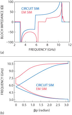
Fig. 2 The bloch impedance (a) and dispersion diagram (b) of the CRLH ZOR UWB BPF.
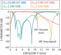
Fig. 3 Circuit and EM simulated S-parameters of the UWB BPF.
where ZR, ZL, WcR and WcL correspond to the RH impedance, LH impedance, the exact LH highpass and RH lowpass cutoff frequencies, respectively. ZR and ZL should be identical to Z0, meeting the balanced condition. WcR and WcL determine the band of the CRLH BPF. The design is carried out with Z0 = 45 Ω, WcL = 3.1 GHz and WcR = 10.6 GHz and the parameters in Equation 1 are calculated as CR = 0.943 pF, LR = 1.91 nH, CL = 0.404 pF and LL = 0.817 nH. To physically implement the equivalent circuit, a center-tapped ZOR BPF is assumed and the corresponding geometrical values are found through iterative electromagnetic (EM) simulations, using ADS Momentum. To check the performance of the circuit and the physical structure, the Bloch impedance and the dispersion diagram are depicted in Figure 2. In the Bloch impedance graph, the ± means the characteristic impedance for positively and negatively traveling waves, respectively. The ZOR can be seen as a metamaterial property at the center frequency between the LH and RH regions. Particularly, the circuit and EM results have a gap, due to the mismatched Bloch impedance of zero and high magnitude over the passband and a discrepancy between the circuit and EM structures. To remove the gap, a matching part is added to the center-tapped ZOR and the total length of this BPF becomes 0.69 × 0.73 λg. Its S-parameters are shown in Figure 3, with a fractional bandwidth greater than 100 percent and an insertion loss less than 1 dB. The return loss does not look perfect, but will get better by more tuning. The serious problem of this BPF is the stopband. Therefore, for its improvement, the second step of the design is carried out by suggesting a compact BSF to be combined with the BPF as shown in Figure 4. The BSF is assumed as the duality of the CRLH to form a wide stopband, geometrically expressed as the shunt relation of interdigital coupled lines and a stepped impedance branch. The circuit of the BSF with cut-off frequencies of 10.8 GHz and 27 GHz is calculated with CL,dual = 0.2 pF, CR,dual = 0.15 pF, LL,dual = 0.3 nH and LR,dual = 0.62 nH. These result in Lf = 1.04 mm, Lc = 1.75 mm, Ll = 2 mm, Lpl = 0.6 mm, Ls = 0.6 mm, G = 0.19 mm, Ge = 0.16, Wf = 0.16 mm, Wfeed = 0.17 mm, Wc = 0.17 mm and Wl = 0.12 mm. Using these elements, the BSF has the size of 0.35 × 0.27 λg. The frequency response of its combination with the BPF is shown in Figure 5. With a small change in the passband from the BPF, the stopband is improved significantly from 11 GHz up to 18 GHz where |S21| is lower than ≤–20 dB from -7.2 dB by the duality of a CRLH type BSF whose size is 0.35 0.27 λg.
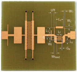
Fig. 4 CRLH ZOR UWB BPF combined with a compact bandstop filter.
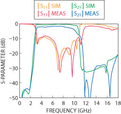
Fig. 5 Simulated and measured S-parameters of the CRLH ZOR UWB combined with the compact bandstop filter.
Conclusion
A center-tapped ZOR UWB BPF has been designed to have an improved stopband by being cascaded with a compact BSF. The novel CRLH ZOR BPF has the size of 0.69 × 0.73 λg with a bandwidth greater than 100 percent and an insertion loss less than 1 dB. Its stopband has an enhanced |S21| –20 dB from –7.2 dB by the duality of a CRLH type BSF whose size is 0.35 × 0.27 g.
Acknowledgment
This work was supported by the University of Incheon Research Promotion Grant.
References
1. H. Ishia and K. Araki, “Design and Analysis of UWB Bandpass Filter with Ring Filter,” 2004 IEEE MTT-S International Microwave Symposium Digest, pp. 1307-1310.
2. H. Wang, L. Zhu and W. Menzel, “Ultra-wideband Bandpass Filter with Hybrid Microstrip/CPW Structure,” IEEE Microwave and Wireless Components Letters, Vol. 15, No. 12, December 2005, pp. 844-846.
3. W. Menzel, M.S.R. Tito and L. Zhu, “Low-loss Ultra-wideband (UWB) Filters Using Suspended Stripline,” Proceedings of the 2005 Asia-Pacific Microwave Conference, pp. 2148–2151.
4. C. Caloz and T. Itoh, Electromagnetic Metamaterials: Transmission Line Theory and Microwave Applications, Wiley-Interscience, John Wiley & Sons Inc., Hoboken, NJ 2006.
5. M. Gil, J. Bonache, J. Garcia, J. Martel and F. Martin, “Composite Right/left-handed Metamaterial Transmission Lines Based on Complementary Split-rings Resonators and Their Applications to Very Wideband and Compact Filter Design,” IEEE Transactions on Microwave Theory and Techniques, Vol. 57, No. 6, June 2007, pp. 1296-1304.
6. G. Jang and S. Kahng, “Design of a Dual-band Metamaterial Bandpass Filter Using Zeroth Order Resonance,” Progress in Electromagnetics Research C, Vol. 12, 2010, pp. 149-162.
7. G. Jang and S. Kahng, “Design of a Metamaterial Bandpass Filter Using the ZOR of a Modified Circular Mushroom Structure,” Microwave Journal, Vol. 54, No. 5, June 2011, pp. 158-167.
Sungtek Kahng received his Ph.D. degree in electronics and communication engineering from Hanyang University, Korea in 2000, with a specialty in radio science and engineering. From 2000 to early 2004, he worked for the Electronics and Telecommunication Research Institute on numerical electromagnetic characterization and developed RF passive components for satellites. In March 2004, he joined the Department of Information and Telecommunication Engineering at the University of Incheon where he has continued research on analysis and advanced design methods of microwave components and antennas, including metamaterial technologies, MIMO communication and wireless power transfer.
Dongjin Lim received his B.E. degree from the University of Incheon (UI), Incheon, Korea, in 2010. He is currently working toward the M.S. degree on radio science and engineering at the Department of Information and Telecommunication Engineering in the University of Incheon. His research fields are microwave engineering, RF components and metamaterials.