
A quarter substrate integrated waveguide resonator (QSIWR) and a fractal-shaped defected structure (FDS) are used to design miniaturized substrate integrated waveguide (SIW) bandpass filters. With the QSIWR, a conventional SIW filter can be reduced in size by approximately 75 percent and the size can be further reduced with FDS. Using QSIWR and FDS, a type of one-pole and a type of two-pole bandpass filters are proposed and optimized. The two-pole bandpass filter has more merits, such as a simple structure, compact size and an extra transmission zero in the upper stopband. The measured and simulated results of a two-pole filter are in good agreement.
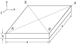
Figure 1 Schematic of the square waveguide resonator.
In recent years, there has been a growing interest in the SIW technology,1-8 which has the advantages of light weight, high power capacity and easy integration with other planar microwave circuits. But, compared to microstrip circuits, the SIW circuits are of larger sizes, especially in low microwave frequency bands. By using half mode substrate integrated waveguide (HMSIW)3-6 and substrate integrated folded waveguide (SIFW)8 structures, the total size of a SIW is nearly reduced by a half, but still keeps comparable performances.
Many kinds of miniaturized filters4,5,7 and antennas6 have been proposed using these technologies. The propagation modes of SIW are similar to those of a rectangular waveguide, so cavity resonators are the basic shapes used in the design of SIW filters. Utilizing the symmetry of SIW, the HMSIW is obtained by cutting the SIW along the perfect magnetic wall. It still keeps half of the field distribution of the dominant mode TE10. The same idea can be applied to shrink the square SIW resonator. By cutting the square SIW resonator along magnetic walls, a quarter SIW resonator (QSIWR) is derived. Using QSIWR, two types of bandpass filter are proposed, achieving approximately a 75 percent reduction in size compared to conventional ones. At the same time, the fractal-shaped9-11 defected structures (FDS) are etched in the QSIWR, which can further reduce the filters’ size and improve their selectivities.

Figure 2 Electric field distribution of a square SIW (a) and QSIWR.
Quarter Substrate Integrated Waveguide Resonator
In Figure 1, if the width of the rectangular resonator is equal to the length a, the TE101 mode can be expressed as follows, which is the same as the square SIW resonator.1
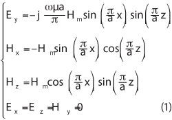
According to Equation 1, the magnetic field intensity H perpendicular to the Plane AA’ (x = z) and the plane BB’(x = -z) are similar, so at the fundamental resonant mode (TE101), the AA’ and BB’ planes are equivalent to perfect magnetic walls. On the condition that the substrate is very thin, by cutting along AA’ and BB’, quarter SIW resonators are left. The QSIWR’s open sides are nearly equivalent to perfect magnetic walls. As shown in Figure 2, comparing with the electric fields of SIW and QSIW, the field is kept almost undamaged. There is only a small wave leakage along two magnetic walls. So the QSIWR can be used to design various cavity filters with 75 percent reduction in size.

Figure 3 One-pole QSIWR with a fractal-shape structure.

Fractal One-Pole Filter Using QSIWR
In order to verify the resonant characteristics of QSIWR, first a new fractal one-pole filter is designed, which is shown in Figure 3. The geometry of QSIWR is a right angled isosceles triangle (RAIT). Two microstrip feed lines are at the center of each right-angle side. The 50 Ω microstrip line with Er = 2.2 and loss tangent of 0.0009, height h = 0.508 mm, conductor strip width w = 1.58 mm is chosen for all filters. At the same time, the diameter of the vias is d = 0.5 mm and the pitch between vias is p = 1.1 mm. The resonant frequency is mainly decided by the hypotenuse length b.1 To lower the resonant frequency, a RAIT defected structure is etched in the center of its upper metal plane. The final dimensions are listed in Table 1. As shown in Figure 4, comparing with the filter without fractal structure, the resonant frequency of the filter with fractal structure shifts to a lower frequency, which is approximately 4.67 GHz, the -3 dB bandwidth is approximately 0.98 GHz. For only one cavity with one resonant mode, there is only one pole in the passband and the upper stopband is not satisfied.
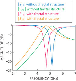
Figure 4 S-parameters for the one-pole QSIWR filters, with and without fractal structure.
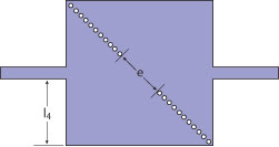
Figure 5 Two-pole bandpass filter with QSIWR.
Fractal-Shaped Two-Pole Filter Using QSIWR
To widen the usefulness of the QSIWR, a kind of two-pole filter is proposed. Figure 5 depicts the main configuration of this filter. First, two identical QSIWR are set back to back. With the central metal vias removed, the remaining vias act as the inductive iris. The microstrip feed lines are placed at the symmetrical sides of the filter. The resonant frequency f0 of this filter is specified at 4.5 GHz with a fractional bandwidth (FBW) of 12 percent. A two-order Chebyshev lowpass filter with passband ripple of 0.01 dB is chosen as the prototype.12 The main factors of the two-pole filter are as follows: M12 = 0.28047, Qei = 3.74083, Qeo = 3.74089.

Figure 6 S-parameters for two-pole QSIWR filter with and without fractal structure.
M12 denotes the coupling coefficient between two neighbor resonators and Qei and Qeo are the input and output external quality factor, respectively. Keeping the diameter of the vias d and the pitch p between vias unchanged, the other size parameters of the two-pole filter are as follows: l4 = 7.5 mm, e = 9.82 mm. As shown in Figure 6, in the whole passband, the insertion loss is approximately 1.2 dB and the return loss is better than 20 dB from 4.40 to 4.62 GHz, the -3 dB bandwidth is approximately 0.6 GHz. The rejection is improved, especially at the upper stopband.
To make the filter more compact, Sierpinski triangles are etched in this two-pole filter. Its fractal dimension is D =In 3/In 2 =1.585.11 As shown in Figure 7, three identical RAITs are etched in the center of each QSIWR. The fractal structure has a distinct effect on the transmission zero of the right side, which makes the filter have a sharp attenuation in the upper stopband. By optimizing the distance q equivalent to two inductive irises and the length j of the right-angle side, the passband shifts to a lower frequency dramatically. The dimensions of the RAIT are as follows: k =6.52 mm, q =14.1 mm, j =8 mm. The simulated and measured results agree well, as shown in Figure 7. With the dimensions of QSIWR unchanged, the resonant frequency of the filter using fractal structures is 3.86 GHz. One transmission zero with an attenuation of 56.9 dB is implemented at 6.13 GHz, which highly improve the selectivity of the upper stopband. The fractal structure plays an important role in improving the performance of the two-pole filter; it perturbs the fields of QSIWR and couples well with the two QSIWRs. This fractal structure affects the filter’s transmission zero, bandwidth and return loss in the passband. At the same time, it makes the filter more compact.

Figure 7 Two-pole bandpass filter with fractal-shape QSIWR (a) layout and (b) photograph.
Conclusion
In this article, according to the magnetic walls theory, a new quarter substrate integrated waveguide resonator is first proposed. Then a fractal-shaped structure is etched off the QSIWR, which makes the QSIWR’s resonant frequency shift to a lower frequency. Then, a fractal-shaped QSIWR is used to design a two-pole bandpass filter. Compared to the filter without a fractal-shaped structure, the fractal-shaped one has many advantages, such as lower resonant frequency, more compact dimensions and high selectivity in the upper stopband. In short, the proposed fractal-shaped QSIWR can significantly shrink the filter’s size and improve the filters’ selectivity, which extend the usability of these shrunk resonators in filter applications.
Acknowledgment
This work is supported by the Fundamental Research Funds for the Central Universities (2010QNA49).
References
- R.Q. Li, X.H. Tang and F. Xiao, “Substrate Integrated Waveguide Dual-mode Filter Using Slot Lines Perturbation,” IET Electronics Letters, Vol. 46, No. 12, June 2010, pp. 845-846.
- X.P. Chen and K. Wu, “Substrate Integrated Waveguide Cross-coupled Filter with Negative Coupling Structure,” IEEE Transactions on Microwave Theory and Techniques, Vol. 56, No. 1, January 2008, pp. 142-149.
- W. Hong, B. Liu, Y. Wang, Q.H. Lai, H.J. Tang, X. Yin et al, “Half Mode Substrate Integrated Waveguide: a New Guided Wave Structure for Microwave and Millimeter Wave Application,” 2006 Joint 31st International Conference on Infrared and Millimeter Waves and 14th International Conference on Terahertz Electronics Proceedings, pp. 219-219.
-
Y. Wang, W. Hong, Y. Dong, B. Liu, H.J. Tang, J. Chen et al, “Half Mode Substrate Integrated Waveguide
(HMSIW) Bandpass Filter,” IEEE Microwave and Wireless Components Letters, Vol. 17, No. 4, April 2007, pp. 265-267. - X. Zhang, J. Xu, Z. Yu and Y.L. Dong, “C-band Half Mode Substrate Integrated Waveguide (HMSIW) Filter,” Microwave and Optical Technology Letters, Vol. 50, No. 2, February 2008, pp. 275-277.
- Y.J. Cheng, W. Hong and K. Wu “Millimeter-wave Half Mode Substrate Integrated Waveguide Frequency Scanning Antenna with Quadri-polarization,” IEEE Transactions on Antennas and Propagation, Vol. 58, No. 6, June 2010, pp. 1848-1855.
- C.H. Zhang, W. Hong, X.P. Chen, J.X. Chen, K. Wu and T.J. Cui, “Multilayered Substrate Integrated Waveguide (MSIW) Elliptic Filter,” IEEE Microwave and Wireless Components Letters, Vol. 15, No. 2, February 2005, pp. 95-97.
- N. Grigoropoulos, B. Sanz-Izquierdo and P.R. Young, “Substrate Integrated Folded Waveguides (SIFW) and Filters,” IEEE Microwave and Wireless Components Letters, Vol. 15, No. 12, December 2005, pp. 829-831.
- D. Oloumi, A. Kordzadeh and A.A.L. Neyestanak, “Size Reduction and Bandwidth Enhancement of a Waveguide Bandpass Filter Using Fractal-shaped Irises,” IEEE Antennas and Wireless Propagation Letters, Vol. 8, No. 24, November 2009, pp. 1214-1217.
- H.X. Xu, G.M. Wang and C.X. Zhang, “Fractal-shaped UWB Bandpass Filter Based on Composite Right/left Handed Transmission Line,” IET Electronics Letters, Vol. 46, No. 4, April 2010, pp. 285-287.
- S. Hebib, H. Aubert, O. Pascal, N. Fonseca, L. Ries and J.M.E. Lopez, “Sierpinski Pyramidal Antenna Loaded with a Cutoff Open-ended Waveguide,” IEEE Antennas and Wireless Propagation Letters, Vol. 8, No. 5, May 2009, pp. 352-355.
- J.S. Hong and M.J. Lancaster, Microstrip Filters for RF-Microwave Applications, John Wiley & Sons, New York, NY, 2001.