
A miniaturized, integrated broadband surface acoustic wave (SAW) antenna with a size of 8.4 × 6.8 mm is designed on a 0.5 mm thick, 128°-rotated Y-cut lithium niobate (LiNbO3) piezoelectric substrate. The antenna is constructed using four cross-coupled half-wavelength square open-loop strips and two 16 µm width interdigital transducers (IDT) of 42 pairs. Photolithography and evaporation techniques are used to realize the designed pattern. The proposed antenna has a -10 dB bandwidth of 2.2 GHz (4.8 to 7 GHz) for WLAN/WiMAX bands applications. The gain and far-field radiation patterns of the proposed antenna are also developed in this study.
Broadband antennas have aroused high interest in recent years for application to multimode wireless communication systems. Because of low cost and process simplicity, printed monopole antennas are very popular candidates for these applications. One of the major challenges is the design of terminal antennas that are compact in size but have a wide impedance matched band. Many kinds of broadband antennas have been studied.1-3 Most printed circuit boards (PCB), made of FR-4 which has a relative permittivity of approximately 4.4, could not be used to fabricate antennas with smaller sizes, and they could be difficult to integrate in radio frequency/microwave circuitry. SAW devices have been widely fabricated and played an important role in wireless communication systems4,5 because the SAW devices had the advantages of low manufacturing cost, miniaturization, lightweight, easy realization, easy integration and better isolation between the radiating element and feeding network. The proposed broadband SAW antenna can be easily integrated with other circuit components to form a complete system. Details of the antenna design and performances are presented.
Antenna Structure and Design
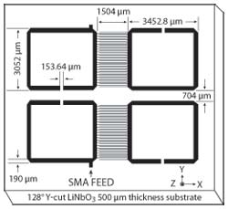
Figure 1 Geometry of the proposed SAW broadband antenna.
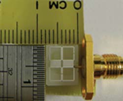
Figure 2 Photograph of the proposed SAW broadband antenna.
Figure 1 shows the geometry of the proposed SAW broadband antenna for WLAN/WiMAX bands applications. This antenna is fabricated on a 128°-rotated Y-cut lithium niobate (LiNbO3) piezoelectric substrate, with a thickness of 0.5 mm. A 50 Ω SMA connector was welded as the input. As shown, this antenna is composed of two parts, which are four cross-coupled half-wavelength square open-loop strips and two 16 µm width interdigital transducers (IDT) of 42 pairs. The IDTs consist of interleaved metal electrodes, which are used to launch and receive the waves, so that an electrical signal is converted to an acoustic wave and then back to an electrical signal. The IDTs not only are the lumped capacitors, but play the role of transducers. The half-wavelength square open-loop strip determines the resonant frequencies.
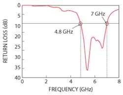
Fig. 3 Measured return loss for the proposed SAW broadband antenna.
When the LiNbO3 piezoelectric substrate is used to fabricate the microwave devices, Aluminum (Al) can be used to print the needed patterns of designed electrodes. The printed method did not need to use a FeCl3 solution to etch the Cu plate from the surfaces of PCBs. Another important reason for us to use the photolithographic technology was that it was easy for mass production and integration. As the parameters showed, the designed antennas had a small size of 8.4 × 6.8 mm, which was much smaller than the monopole antennas fabricated on an FR4 substrate. The photograph of the fabricated SAW antenna under the optimal parameters is shown in Figure 2. Finally, the characteristics of fabricated antennas were measured using a vector network analyzer and a far-field measurement system.
Results and Discussions
The measurement of return losses is carried out with an HP8720C network analyzer. Figure 3 shows the measured return losses of the proposed broadband SAW antenna. The -10 dB bandwidth for the measured return losses reaches 2.2 GHz (4.8 to 7 GHz), and can cover the 5.15 to 5.35 GHz and 5.725 to 5.825 GHz WLAN bands, as well as the 5.25 to 5.85 GHz WiMAX bands. The measured far-field radiation patterns of the integrated broadband SAW antenna in x-y, x-z and y-z plane at 5.4 and 6.6 GHz are depicted in Figure 4. The patterns are observed to be stable for operation at the two operating frequencies. In the xz-plane, the patterns are all nearly omni-directional, and in the xy-plane, as expected, are all very monopole-like.
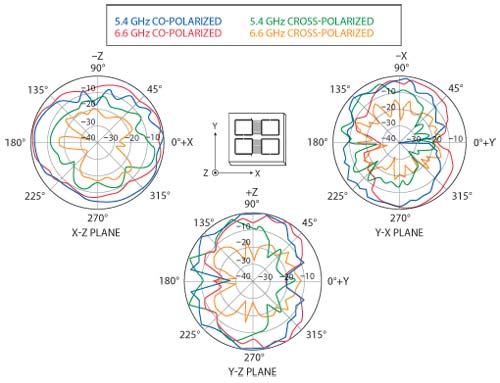
Figure 4 Measured radiation patterns of the proposed SAW broadband antenna at 5.4 and 6.6 GHz.
Figure 5 shows the measured antenna gain. The antenna gain varies from approximately -11 to -7 dBi for frequencies over the entire band. According to S. Masaaki’s Figure 4,6 the result shows that when the electrical length of the antenna is reduced, the antenna gain is also reduced. Although the antenna gain is not perfect, it can be integrated with the active components to increase the antenna gain.
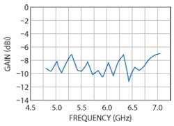
Fig. 5 Measured gain of the proposed SAW broadband antenna.
Conclusion
A compact integrated SAW antenna with broadband performance is designed and fabricated on 128°-rotated Y-cut LiNbO3 piezoelectric substrate, using photolithography and evaporation techniques. This antenna is composed of four cross-coupled half-wavelength square open-loop strips and two 16 µm width IDTs of 42 pairs. The proposed broadband SAW antenna can be designed to have a bandwidth of 2.2 GHz (4.8 to 7 GHz), good radiation performance and antenna gain varying from approximately -11 to -7 dBi for frequencies over the operating band, but is only 8.4 × 6.8 mm in size. This antenna is especially suited for WLAN/WiMAX applications in small-size signal receptions and handheld mobile devices. The proposed antenna is easy to fabricate and integrated with radio frequency/microwave circuitry for low manufacturing cost.
Acknowledgment
This research work was supported by the National Science Council of the Republic of China, under the grant number NSC 98-2221-E-024-016.
References
- I.F. Chen and C.M. Peng, “Printed Broadband Monopole Antenna for WLAN/WiMAX Applications,” IEEE Antennas and Wireless Propagation Letters, Vol. 8, 2009, pp. 472-474.
- Z.A. Zheng and Q.X. Chu, “CPW-fed Ultra-wideband Antenna with Compact Size,” Electronics Letters, Vol. 45, No. 12, June 2009, pp. 593-594.
- R.W. Carson, J.S. Hyok and E. Yasan “A Wideband Stick-on Connector for CPW-fed On-glass Antennas,” IEEE Antennas and Wireless Propagation Letters, 2010, Vol. 9, pp. 171-174.
- C.K. Cambell, Surface Acoustic Wave Devices for Mobile and Wireless Communication, Academic Press Inc., 1998.
- D. Supriyo, Surface Acoustic Wave Devices, Prentice Hall, Englewood Cliffs, 1986.
- S. Masaaki, “Small or Low Profile Antennas and Radio Communication Systems,” IEICE Transactions on Communications, 1988, Vol. J71-B, No. 11, pp. 1198-1205.