
Mobile subscribers increasingly require high data rate applications as the amount of wireless Internet devices continuesto rise. Therefore, higher spectrum efficiency and network capacity are required to keep these end-users satisfied and their applications working efficiently. High levels of application data use can be achieved by multi-antenna technologies, adaptive radio links, advanced network and multi-radio technologies. The complexity of user devices and wireless systems is increasing, due to the need for continuous system adaptation to the prevailing multi-dimensional radio channel conditions. One key driver is the multi-antenna technology, multiple-input, multiple-output (MIMO), which comprises spatial multiplexing, spatial diversity and beamforming. The technology development sets challenging requirements for radio channel modeling and emulation as well as for the testing of wireless communication networks, since the MIMO performance depends strongly on radio channel characteristics. Accordingly, the required capacity of radio channel emulators is increasing constantly, as performance verification for more and more complex wireless systems is needed.
Several trends in wireless testing have been observed during the evolution of mobile technology from 2G to 4G and beyond. Four of them are directly related to radio channel modeling and emulation, namely trends from single-input, single-output (SISO) to MIMO, from conductive to Over-the-Air (OTA), from link to network and from a single network to multiple networks testing. Emulation of realistic channel models is crucial since the state-of-the-art wireless communications systems, such as LTE, adapt both the multi-antenna transmission (TX) and reception (RX) to the continuously changing radio channel. Due to the importance of radio channel emulation in these trends, channel models are reviewed first.
Multi-antenna channel models can be categorized in site-specific geometric models, site-independent stochastic channel models (that is correlation matrix based models) and Geometry-based Stochastic Channel Models (GSCM). Correlation matrix-based models are used in LTE user equipment (UE) conformance tests,1 and in IEEE 802.11n and 802.11ac specifications.2,3 The GSCM models rely on the geometry of propagation paths and antenna arrays, which makes it possible to test different antenna constellations with the same propagation model. These include 3GPP/3GPP2 Spatial Channel Models,4 WINNER5 and ITU-R IMT-Advanced models.6
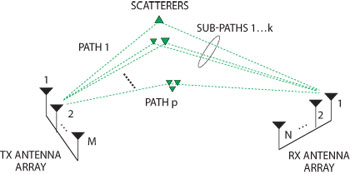
Fig. 1 MIMO channel geometry showing TX and RX antenna arrays and propagation paths.
GSCM takes into account all four dimensions of the radio channel (frequency, time, space and polarization). It does not explicitly specify the locations of the scatterers, but rather the directions of the paths. The channel parameters for individual snapshots are determined stochastically from statistical distributions extracted from radio channel measurements. Antenna geometries and radiation patterns can be defined separately. Channel realizations are generated by summing contributions of propagation paths with specific small-scale parameters like delay, power, angle-of-arrival (AoA) and angle-of-departure (AoD). Superposition of paths results in a correlation between antenna elements and temporal fading with geometry dependent Doppler spectrum.
Elements of the MIMO channel are illustrated in Figure 1, where each path consists of multiple sub-paths. The time variant impulse responses for any TX-RX antenna pair can be calculated in the GSCM model from the geometry as follows:
where t is time, τ is delay, p is the number of paths, k is the number of sub-paths, and Frx and Ftx'; are the element-wise antenna array dual-polarized field patterns for RX and TX, respectively. Ap, k is the dual-polarized complex gain matrix of sub-path p, k, Φp,kis the AoD unit vector, φp,k is the AoA unit vector and vp,k is the Doppler frequency component of sub-path p, k. For more details, see references 5 and 6. All the parameters of Equation 1 can be based on measurements or theory. Equation 1 indicates that radio channel models are becoming more accurate. Testing of wireless systems with multi-dimensional channel models is essential in each of the four trends described below.
Fig. 2 From SISO to MIMO testing.
Trend 1: From SISO to MIMO
The first trend in wireless testing is from a single-antenna SISO radio to multi-antenna MIMO radios (see Figure 2). The capacity requirements of a MIMO channel emulator grow significantly along with the number of TX/RX antennas involved in the system. Conventional testing has focused on SISO devices with test instruments connected to antenna connectors. Such tests include conformance tests, which verify that a product meets the minimum requirements of a certain radio technology. For example, the 3GPP has defined product conformance tests for LTE devices. These tests specify radio channel models that are typically relatively simple tapped delay line models, in which the received signal y(t) is calculated via the convolution of a transmitted signal x(t) and a time variant impulse response h(t,τ) as follows:
where * pdenotes convolution. The processing requirement (number of multiplications per second) C for the SISO case can be calculated as

where B is the bandwidth and L is the number of taps. D denotes duplexing (D =1: no duplexing, D =2: duplexing) and the multiplier 4 comes from complex multiplication.
In MIMO testing, the number of fading channels is N × M, where N and M are the number of RX and TX antennas in the system. The LTE supports up to 4×4 MIMO mode (Rel. 8) and up to eight TX-antennas in beamforming-MIMO mode (Rel. 9). In the future, the LTE-Advanced (Rel. 10) defines an 8×8 MIMO mode, increasing the testing capacity requirements further. The number of multiplications per second in MIMO tests can be calculated from

where the needed testing capacity increases significantly compared to the SISO case.
Another new element in MIMO systems is the correlation between device under test (DUT) antennas. The MIMO performance depends strongly on the correlation of device antenna signals, which necessitates advanced channel models. GSCM channel models apply simulated or measured antenna characteristics and therefore are capable of producing realistic correlations. This is important when modeling:
- Delay spread (frequency diversity)
- Doppler spread (time diversity)
- Angle spread/antenna separation (space diversity)
- Polarization (polarization diversity)
The MIMO radio channel changes dynamically at the rate defined by the Doppler characteristics. With this rate, the adaptive radio link adjusts the data transmission to the instantaneous MIMO radio channel state. In the case of high Signal-to-Interference-and-Noise Ratio (SINR) at a receiver, the transmitter can maximize the data rate by applying parallel data streams (spatial multiplexing), together with high-order modulation. This is possible only with favorable MIMO channel conditions. Obviously, in real life, the optimum channel conditions are rarely available, which underlines the importance of testing the MIMO performance in various radio channel conditions. GSCM models are well suited for this.
Advanced performance testing is needed to verify the actual MIMO device performance. By validating products with reliable performance tests, vendors and operators can gain a competitive advantage on the market by achieving better product quality with shorter development time and lower costs.
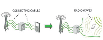
Fig. 3 From conductive to OTA testing.
MIMO conductive testing is important for radio product development covering several essential aspects such as the baseband chipset, radio module and system testing in R&D. However, ultimate testing also requires accurate models of the base station (BS) and mobile terminal (MT) antennas and RF characteristics. The need for authentic RF modeling with the actual device antennas leads to MIMO OTA testing, which together with conductive testing, increases test effectiveness and validity.
Trend 2: From Conductive to OTA Testing
The second trend is toward OTA testing (see Figure 3). OTA testing employs radio waves, revealing the performance of the DUT with its final antenna and RF design. MIMO OTA testing reveals the end-to-end performance of the entire DUT, while conductive testing totally omits the antenna impact. OTA testing offers a very realistic testing solution to speed-up the development process and to verify the DUT performance in normal operation. Most MTs have integrated antennas, which cannot be separated without affecting the RF performance. This is the main reason why OTA testing is widely applied in SISO systems. However, it is even more important for MIMO systems, since the system performance is dictated largely by the correlation between antenna signals. This correlation depends on actual RF/antenna design and can be defined by the equation:7
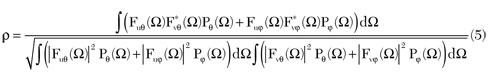
where F denotes the antenna pattern and P the power angular spectrum of radio waves, Ω the angle variable, u,v to the antenna indexes and φ, θ to the polarization directions. This equation indicates that antenna and propagation effects have to be tested jointly.
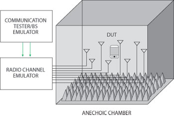
Fig. 4 Anechoic chamber-based MIMO OTA.
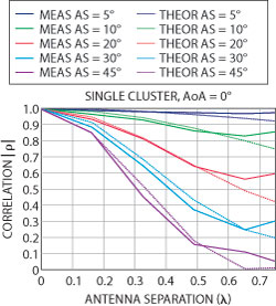
Fig. 5 Measured spatial correlation.
The number of multiplications per second in MIMO OTA tests can be calculated from
where NOTA is the number of probe antennas (typically much larger than the number of the DUT antennas, N).
In MIMO OTA testing, the DUT is located in an anechoic chamber and the propagation environment is created by a number of probe antennas and a radio channel emulator (see Figure 4). The setup enables the creation of a predefined radio environment that can be repeatedly applied. A measurement-based GSCM model can be used to create the desired propagation environment. OTA requires mapping of the channel model to the probe antenna constellation. Additionally, the antenna weights are optimized for the desired AoA distribution after calibrating for the effects of cabling, RF and probe antennas. The test setup can be optimized according to the size of the DUT.
The accuracy of the MIMO OTA technique has been verified via measurements. The most important parameter in MIMO testing is the antenna signal correlation, which can be verified by dipole antenna measurements. Figure 5 shows the measured correlation for several different angle spreads (AS) using eight probe antennas. The correlation depends strongly on the antenna separation and the angular spread of impinging radio signals. The result is well in line with the theoretical one. Accordingly, the MIMO OTA is able to generate a wide variety of radio environments with large, medium or low correlation. Figure 5 shows that the accuracy is degrading as the DUT size is growing. However, if the number of probe antennas is increased to 16, the DUT size can be doubled. More validation results are available.8
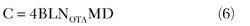
MIMO OTA testing allows performance comparison of commercial off-the-shelf devices giving the actual end-user experience with specific user applications. As an example, commercial LTE terminals have been tested showing the throughput dependence on the actual radio channel environment and on the MT itself (see Figure 6). UE1 clearly performs better. It achieves a peak throughput at 4 dB smaller signal level in UMi than in UMa, due to lower antenna signal correlation (AS is larger in UMi). Single link testing focuses mainly on the physical layer testing of a single BS and a single MT. A more complete picture of the overall system performance is obtained only when the test setup includes multiple BSs and MTs.
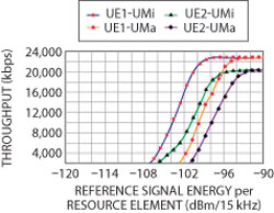
Fig. 6 Throughput measurements in urban micro (UMi) and macro (UMa) cells using two different MTs (UE1 and UE2).
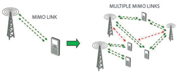
Fig. 7 From link to network.
Trend 3: From Link to Network
Single link to multi-link (from link to network level) is the third trend in wireless testing (see Figure 7). The complexity of a MIMO channel emulator grows exponentially with the number of BSs and the MTs. The importance of multi-link testing is growing due to the need for maximizing the overall system performance (throughput, spectral efficiency and latency). Optimizing only the link level performance is not sufficient, since interference is a major limiting factor in a multi-cell and multi-user environment. In advanced wireless IP networks (such as in LTE), the system performance relies strongly on cross-layer algorithms such as the Medium Access Control (MAC) and Radio Link Control (RLC) layers, which coordinate the efficient utilization of physical layer radio resources. The MAC and RLC layers have a key role in scheduling data packets to each MT during their best possible MIMO radio channel state and, at the same time, minimizing multiuser and multi-cell interference. Wideband MIMO technology enables dynamic scheduling in space, time and frequency domains, which provides additional freedom in system performance enhancement.
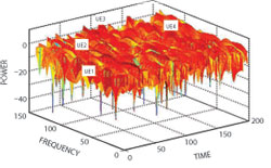
Fig. 8 Example of shared radio allocation for four users in one cell area.
Figure 8 shows an exemplary allocation of four MTs at their preferred time-frequency resource block scheduled by the BS on one physical cell at one time instant. Each of them is given such a time-frequency block, which provides good link performance. In LTE downlink the smallest schedulable resource block corresponds to a bandwidth-time unit of 180 kHz by 1 ms consisting of 12×14 OFDMA subcarriers. High spectral efficiency of LTE is based on adaptive MIMO radio with advanced cross-layer algorithms, such as the packet scheduling in BSs. The scheduler implementation is vendor specific, so that the system performance may vary significantly among different products depending on, for instance, radio channel environments and system load scenarios. To assist scheduling, each terminal reports its multidimensional radio channel state information to the serving BS, including Channel Quality Indicator, Pre-coding Matrix Indicators and Channel Rank Indicators.9 Based on this information and on the intra- and inter-cell interference condition, each BS is able to coordinate the use of dynamic multiuser MIMO radio channel, using best possible MIMO modes. Clearly, the LTE system performance is directly proportional to instantaneously and continuously changing MIMO channel characteristics as well as on prevailing system interference. This type of multiuser MIMO system optimization is extremely challenging.
Realistic system level testing in laboratory requires complete MTs and BSs with all functionalities. Figure 9 illustrates such a multi-user and multi-cell MIMO test scenario, where the radio channel emulator produces numerous real-time MIMO channels. The system performance of a multi-cell, multi-user network can be evaluated using realistic radio channel environments. Due to the dynamic radio link techniques, it is important that the link adaptation can be repeatedly tested in desired MIMO scenarios with predefined radio channel environments, such as in application level testing.10 One interesting topic is the coordination of inter-cell and intra-cell interference.
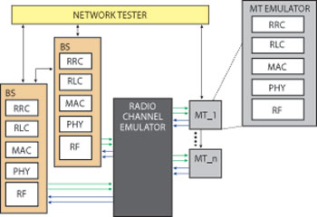
Fig. 9 Test scenario for multiuser system performance evaluation.
GSCM channel models are suitable also for network level performance testing in laboratory conditions, since they support features such as location, antenna height, antenna tilt and mobile route. However, the number of multiplications per second in network emulation grows with the number of radio links R in the network:
For example, modeling of eight BS cells and eight independent mobile users requires a 16×16 MIMO channel emulator, if a basic LTE with a 2×2 MIMO scheme is assumed. Assuming eight users with 4×4 MIMO and eight BS cells, a 32×32 emulator is required. Alternatively, this would allow the model of 16 BS cells and 16 users with a 2×2 MIMO mode.
For a site and multi-site specific performance evaluation, a Virtual Drive Testing (VDT)11 can be performed in laboratory. In VDT, the actual radio channel conditions and network configuration are recorded and taken from field to the laboratory. The recorded channel data are replayed with the radio channel emulator to study handover and throughput performance in an area covering known cells (see Figure 10). The field test can be repeated in laboratory if the radio channel and network configuration data are recorded along the test route. The VDT approach enables laboratory tests to run using measured radio environments of problematic cells, for example. The testing requirements increase further when moving from a single wireless communication network to multiple networks, which deploy the available radio spectrum in different ways.
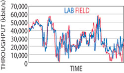
Fig. 10 Site specific LTE throughput test in field and laboratory.
Trend 4: From Single Network to Multiple Networks
The fourth trend is from single network to multiple networks testing. As new technology generations develop, they become available as new additional networks (see Figure 11). Testing heterogeneous networks represents the ultimate challenge from the view point of system testing. Current cell phones are typically equipped with multiband 2G, 3G and WiFi connections – in the near future with LTE. From the beginning LTE networks will be deployed for data traffic, whereas the underlying 2G/3G will provide basic voice services and seamless mobility for wide area coverage. Looking at the future, ITU-R has defined guidelines for IMT-Advanced, which indicate that future, wireless systems should encompass new requirements.12
- High spectral efficiency
- High degree of common functionalities worldwide
- Service compatibility with legacy IMT systems and fixed networks
- Interworking capability with existing wireless systems
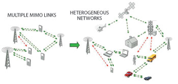
Fig. 11 From single network to multiple networks.
Coordinated use of available radio access systems becomes essential when heterogeneous networks develop further. For efficient use of the limited radio spectrum higher order MIMO, co-operative MIMO, interference coordination and adaptive antenna techniques are used at single network level. In parallel to that, the heterogeneous networks will provide additional methods for balancing the network load. One way is to utilize unlicensed radio access systems such as WiFi, where available, and added features such as device-to-device communications and relaying.
This indicates that cognitive radios become important in exploiting the limited radio resources regardless of their location.13 At the same time, it implies the highest complexity of test systems. There is a need for test system simplification and integration as the demand for testing of heterogeneous networks in realistic conditions is growing. Test systems with multiple frequency bands, dynamic radio channel conditions and propagation models with very wide bandwidths are required. Moreover, hybrid systems bring new challenges to testing (one example being the long propagation delays in satellite radio channels). The GSCM model is a good candidate also for multi-network testing, since it enables adjusting the model accuracy versus complexity.
Summary
The above four trends set high requirements for testing wireless systems in the laboratory and especially for the modeling of the radio channels for complete wireless networks. Test systems will become more advanced due to higher bandwidths, increased number of antennas and multiple radio systems. This requires models with a high number of radio channels. This development indicates also that a higher degree of integration is crucial in advanced test systems. In each trend, the required number of radio channels increases in a multiplicative manner. In addition to the high number of channels, reliability, automation, configurability, usability and versatility of test systems will be also crucial in the future.
References
- 3GPP TS 36.101, 3GPP E-UTRA UE Radio Transmission and Reception (Release 10), V10.1.1 (2011-01).
- V. Erceg, et al., “Indoor MIMO WLAN Channel Models, IEEE 802.11-03/161r2,” September 2003.
- G. Breit, et al., “TGac Channel Model Addendum, IEEE 802.11-09/0308r12,” March 2010.
- 3GPP TR 25.996, Spatial Channel Model for MIMO Simulations (Release 6), V6.1.0.
- P. Kyösti, et al., “IST-WINNER II Deliverable 1.1.2 v.1.2. WINNER II Channel Models, IST-WINNER2. Tech. Rep.,” 2007, www.ist-winner.org/deliverables.html.
- Guidelines for Evaluation of Radio Interface Technologies for IMT-Advanced, Report ITU-R M.2135, 2008.
- R. Vaughan and J.B. Andersen, “Channels, Propagation and Antennas for Mobile Communications,” IET Electromagnetic Wave series 50, IEE, London, UK, 2003.
- Elektrobit, “Verified Performance: Anechoic Chamber and Fading Emulator Based MIMO OTA Method,” R4-103856, 3GPP TSG-RAN WG4 meeting AH#4, Xi’an, China, 11-15 October 2010.
- H. Holma and A. Toskala, LTE for UMTS: OFDMA and SC-FDMA Based Radio Access, John Wiley and Sons, Somerset, N.J. 2009.
- www.testautomation.fi/CrossNet/CrossNet White_Paper_v1-0.pdf.
- www.elektrobit.com/whats_new/newsletters/eb_wireless_newsletter/issue_04/2010/new_features_options_and_baseline_configuration_to_eb_propsim_f8_radio_channel_emulator.
- “Requirements Related to Technical Performance for IMT-Advanced Radio Interface(s),” Report ITU-R M.2134, 2008.
- F.H.P. Fitzek and M.D. Katz, Cognitive Wireless Networks, Springer, New York, N.Y. 2007.