
The cost of failure in many of today’s electrical applications dictates the need for highly reliable RF/microwave cable assemblies — whether failure translates to lost revenue, production downtime, or customer safety. Using ruggedized assemblies has become one of the most common solutions for preserving reliable performance. However, having a ruggedized RF/microwave cable assembly does not necessarily mean the assembly needs to be over-engineered; it simply needs to be properly designed to ensure it is appropriate for the intended use. Understanding the constraints of your application and the environment in which it will be used can ensure that the RF/microwave cable assembly will be properly engineered to provide precise and repeatable measurements with stable electrical performance for your application. Challenges during installation, usage considerations and constraints of the physical environment all affect a cable’s performance.
Installation Constraints
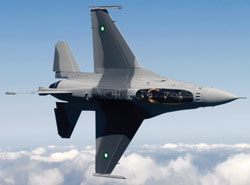
Fig. 1 The tight spaces and routing challenges of installation in an aircraft can easily compromise the performance of RF/microwave cable assemblies.
Where and how the RF/microwave cable assembly will be installed has a direct impact on the long-term reliability of the cable. Understanding the installation process can help determine which materials are best for the assembly’s construction. For example, if the assembly must be routed through a tight space, size and durability should be evaluated. If the assembly will be pulled through a conduit, the cable’s outer jacket also needs to be abrasion-resistant. And, if the assembly needs to be twisted so it can be routed around other equipment, it needs to be very flexible with a small bend radius. All of these situations mean that the cable’s construction needs to withstand the installation and protect the conductors during use (see Figure 1).
If the distance between the two connection points for the cable assembly is very short, signal reflection and voltage standing wave ratio (VSWR) can have an adverse effect on the measurement accuracy. Adding a service loop in the cable can allow more flexibility and help eliminate length tolerance issues.
Usage Considerations
How the RF/microwave cable assembly will be used is another important aspect to consider when selecting the right cable. Like the installation process, the application for which the assembly is intended often defines the type of materials used in the assembly’s construction as well as its performance requirements.
Cable Handling: The first, and probably foremost, consideration is whether the cable will be left in place once it is installed or whether it will be handled frequently. When the cable is connected to equipment handled manually, it is much more likely to experience flexure, and frequent flexing can potentially affect the precision and repeatability of measurements. An operator can kink, pinch, or crush a cable by stepping on it, rolling over it, or wrapping it around a piece of portable equipment during transport. Therefore, tensile strength is essential in overcoming mechanical stress on the cable. Externally ruggedized cables cannot always withstand this type of torque. However, internally ruggedized cables can improve phase and amplitude stability with flexure because they are crush-resistant and maintain excellent tensile strength even at a small bend radius (see Figure 2).
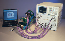
Fig. 2 In a laboratory environment, RF/microwave cable assemblies are frequently bent, twisted and pulled, which can affect the precision and repeatability of measurements (courtesy of Agilent Technologies).
Another consideration for cables that are frequently handled is whether they will be used in a high-throughput application. These applications require frequent attaching and detaching of the cable from the device under test (DUT). Assemblies engineered for this type of application should reduce the need for frequent recalibration and time-consuming troubleshooting due to testing errors. Selecting a reliable RF/microwave cable assembly with a quick-turn connector can also increase throughput by eliminating the need for a torque wrench.
Size Constraints Versus Insertion Loss: For applications that require RF/microwave cable assemblies, insertion loss is usually a critical performance specification. For some applications, the size of the cable assembly is also important, and there can be a trade-off between insertion loss and cable length or diameter. With RF/microwave cable assemblies, loss is directly related to cable diameter. An application may have a specific loss target as well as an overall cable diameter target; however, in some instances, the maximum diameter target could prevent the loss requirement from being met. The combination of longer distance and loss target may mean that the cable needs a larger diameter. In aerospace systems, for example, engineers often specify a maximum cable diameter because smaller cables mean less weight. Reducing the weight of a cable assembly may compromise its durability and electrical performance with use. Choosing a high-quality cable with a lower dielectric constant will translate to a lower loss for a given diameter. However, it is important to focus on the dielectric constant of the finished cable assembly rather than that of the raw materials.
Phase or Time-Delay Matching: RF/microwave cable assemblies may require phase or time-delay matching to ensure that every cable within a set has its time delay or phase length within a specified tolerance range. This type of matching can be either absolute (i.e., one or more assemblies having a specific time delay or phase length target value plus/minus the tolerance) or relative (i.e., a set of assemblies with time delay or phase length within a specified match window). Phase-matched assemblies are usually used in applications with phase-array radar, differential signaling and power combining. For applications that require phase or time-delay matching, it is critical to select a cable assembly that is also phase-stable over flexure so that performance is maintained.
Power Handling at Frequency of Interest: Assemblies are usually specified with an adequate margin of safety to ensure that they can handle the maximum amount of power at the desired frequency range. However, environmental conditions, such as high temperatures, vacuum, humidity, etc., can affect the power requirements. A cable assembly dissipates heat energy using three mechanisms: conduction, convection and radiation. Temperature or pressure changes directly affect the cable’s ability to reduce heat by convection, with a vacuum completely eliminating it. This leaves only conduction through the outer braid and center conductor of the cable assembly and radiation as alternative mechanisms. One of the consequences of these environmental conditions is thermal breakdown caused by heating within the cable and connector due to power dissipation. To understand power handling challenges, it is necessary to understand temperature and pressure requirements as well as the continuous average power value at a specific frequency being put to the cable.
For power handling at certain frequencies, the type of connector used with the RF/microwave cable assembly is also important. Like cable assemblies, connectors are rated based on how they handle power as a function of frequency. Charts are available that detail the power handling capability of various connectors. In addition, since high amounts of power under certain conditions may generate a significant amount of heat, the type of solder used for terminating the connectors should also be considered.
The Physical Environment
The physical environments in which RF/microwave assemblies are being used today are becoming more challenging. Assemblies are being exposed to such conditions as extreme temperatures, vibration and constant electromagnetic interference (EMI). These environmental challenges vary significantly, depending on the application. For example, a cable assembly used in a controlled-environment laboratory encounters very different environmental conditions from one analyzing flight data in an aircraft. Like all constraints, the impact of these environmental challenges can be minimized by selecting a RF/microwave cable assembly engineered to withstand them.
Temperature and Pressure: Temperature and pressure variations can affect a RF/microwave assembly’s VSWR and insertion loss performance. High temperatures increase insertion loss, while low temperatures reduce insertion loss. This is due to thermal effects and their impact on electron activity. VSWR can be altered by physical changes in the assembly as a result of expansion and contraction due to temperature change.
Temperature changes can also affect phase length. As the temperature approaches an extreme, the electrical length will change; if it does not change at the same rate as the temperature when returning to normal (a state known as hysteresis), it is very difficult to apply error-correction techniques to the signal.
Temperature and pressure can also affect the cable’s durability. Low temperatures can make cable materials brittle, and high temperatures cause them to become very soft. Vacuum leaches oils and additives out of certain materials, which could have an adverse effect on a cleanroom manufacturing process.
Vibration: Whether used on a manufacturing floor or in an aircraft, RF/microwave cable assemblies can be exposed to significant shaking and vibration. Phase and amplitude stability during flexure and shake need to be evaluated for any assemblies that will be used in these types of environments. Utilizing a high-quality cable that is phase- and amplitude-stable will provide more precise and repeatable results by preserving the integrity of the signal.
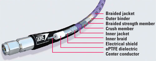
Figure 3 RF/microwave cables with robust shielding at the outer conductor can minimize crosstalk and electromagnetic interference.
Electromagnetic Interference (EMI): Today’s electronic equipment is increasingly complex, with many electrical subsystems generating their own signals, all of which can interfere with the performance of a RF/microwave cable assembly. In addition, assemblies are also being used in environments where high-voltage signals are continually being transmitted. For example, portable test analyzers with RF/microwave assemblies are used in the telecommunication industry to test the performance of cell tower antennas with constant interference that could compromise the integrity of the test measurements. Choosing a cable with robust shielding at the outer conductor will minimize any possibilities of cross-talk or EMI (see Figure 3).
Abrasion and Cut-Through: In addition to being a consideration during the installation process, abrasion and cut-through are constraints that can be found in many environments — aircraft applications, handheld analyzers used in the field, portable equipment around which the assembly is wrapped during transport, etc. Some jacketing materials, such as polyurethane and engineered fluoropolymers, are more abrasion-resistant and durable than others, so potential exposure to abrasive surfaces should be considered when designing a cable assembly for a specific application.
Verifying Performance
Because precise and repeatable measurements are so important with RF/microwave cable assemblies, it is important to discuss with the manufacturer what types of performance testing have been done on the assembly. Mechanical tests — such as a flex test with repeated bending of 180 degrees or more, or the pull test to simulate use as a tether — can verify the assembly’s electrical performance while it is operating under conditions such as crushing, abrasion, potential cut-through and continuous flexing. During these tests, insertion loss and VSWR should be evaluated.
The cable’s electrical performance should also be measured while simulating the physical environment in which it will operate — conditions such as temperature, altitude, pressure and vibration. For example, it is important to monitor impedance during altitude change, mechanical shock and vibration tests. By adding a clamp force during a temperature cycling test, the cable assembly’s dielectric withstanding voltage can be monitored to see how the jacket and conductor change. After the cable is put through substantive mechanical and environmental tests, the manufacturer should again verify that the electrical performance, dielectric and jacket materials remain stable within the requirements of the application.
Conclusion
RF/microwave cable assemblies need to be engineered to withstand demanding applications in which precise and repeatable measurements are essential. Understanding the constraints of an application and the environment in which the RF/microwave cable assembly will be used can ensure that it will be properly engineered to provide consistent, repeatable measurements with stable electrical performance for that application. And performance testing can ensure that the cable will maintain reliable performance. The proper cable assembly can save time and money over the life of the equipment because it can reduce equipment downtime, eliminate cable failure and increase service life.