
A stripline based dual-band 3 dB tandem hybrid coupler employing a minimal number of coupled transmission line elements has been developed. The topology, utilizing two single-section component hybrids in a cascade (tandem), allows for two perfect 3 dB (plus insertion loss) power split points (crossover points) below and above the center frequency of the couplers. The frequencies of the perfect split may differ by a factor of three or greater depending on the center frequency coupling value of either component coupler. A 90° output phase shift consistency, natural for coupled line-based hybrids (backward couplers) and maintained between two output ports of each component hybrid over extremely broad frequency range, guarantees a minimized (0.2 to 0.3 dB) axial ratio for moderate width lower and upper frequency regions around the crossover points. A traditional approach, based on cascading of two (or even three) multi-sectional symmetric couplers in tandem,1-3 delivering equal split-over extremely broad frequency band, including two bands (lower and upper) of interest and between, will make the design much more complex and result in extra space required, increased insertion loss and possible significant phase deviation from 90°, especially at the upper part of the operational band. The typical tandem design, based on two identical symmetric multi-section component couplers, has been described.2,3 Each component coupler delivers 8.34 dB and 90° phase shift over a specified bandwidth, in order to deliver 3 dB/90° shift when cascaded. Another solution is an asymmetric tandem of two or even three symmetric couplers.2,3 A 3:1 bandwidth, with 0.02 dB ripple, can be achieved by cascading a five asymmetric and single-section component couplers, as illustrated by H. Howe3 in his table 5-6. In both cases, the 3 dB/90° split is delivered over a broader bandwidth with a number of sections of each component coupler and number of couplers in tandem determined by low and high edge frequencies (edge frequency ratio) and amplitude ripples. The principal difference between the described dual-band hybrid coupler and a traditional one is based on the fact that two single section cascaded component couplers produce two points of “perfect” 3 dB/90° split at given lower and upper frequencies of interest only. The theoretical justification, software simulation and experimental prototype development proved the integrity of the proposed design approach and, particularly, the flexibility in adjustment of the two crossover points of equal power split between two output ports to the specified frequency location. The dual-band hybrid coupler was developed specifically for the circularly polarized signal formation, made possible at the single polarizing antenna, delivering two bands (transmit and receive) circularly polarized signal simultaneously.
Theory
Fig. 1 Dual-band coupler hybrid functional diagram.
Shown in Figure 1 is a functional block diagram of a typical single-section tandem coupler.3 The voltage coupling coefficient at the first component coupler outputs can be found as follows:4
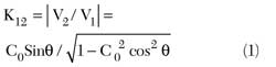
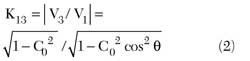
where C0 is the center frequency coupling value of the single coupler and = π/2 + π/2 Δf/f0 is the electrical length of the coupler as a function of the deviation from the center frequency. It should be mentioned that the voltage V3 at the DC output (the output is DC coupled to the input) is naturally 90° behind V2 at the coupled output. Further vector summation of the two signals at the tandem outputs delivers the projected coupling, including a perfect 3 dB split at the crossover frequencies. First, consider the case of two identical couplers cascaded in tandem.
Two Identical Component Hybrids
In order to deliver 3 dB of the overall tandem power split, each component hybrid coupling value at the crossover frequencies should maintain:
K12 = - 8.34 dB (0.383 voltage coupling) at the coupled output3
K13 = - 0.688 dB (0.924 voltage coupling) at the DC output
The ratio between the two coupling coefficients is found to be as follows, η = K13/K12 = 2.4125. Then, equating this number to the voltage ratio |V3|/|V2|, using Equations 1 and 2, the center frequency component hybrid voltage coupling value as a function of the deviation of the cross-over points from the center frequency of the single coupler is obtained:
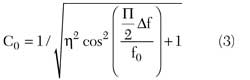
Fig. 2 Component coupler port response (blue) and hybrid tandem response.
Fig. 3 Component hybrid center frequency coupling curve.
As an illustration, Figure 2 shows the simulated response of the component coupler delivering 5.924 dB (0.506 voltage) coupling at the center frequency (f0 = 4760 MHz) and 3 dB at Δf/f0 = ± 0.5 (7140 and 2380 MHz) when both identical couplers are cascaded. As seen from Equation 3, the center frequency coupling value of the component hybrid set the symmetric location of the crossover frequency points Δf/f0 with respect to the center frequency. Shown in Figure 3 is a coupling curve, presenting a component center frequency coupling value as a function of the relative position of the crossover frequency points.
Two Component Hybrids of Arbitrary Coupling
The equal split at the two cross-over points equidistant from center frequency is possible with two-component hybrids of an arbitrary coupling provided that the coupling values meet a certain condition. The main factor of the equal split is that the vector summation of two signals coming to each output (DC and coupled) of the tandem should deliver 0.707 of the input voltage. Considering a tandem signal propagation as shown in Figure 1, the voltages at the DC and coupled outputs now can be written as follows:
where K121 and K122 , K131 and K132 are the voltage couplings of an arbitrary frequency at the coupled and DC outputs of the first and second component hybrids, correspondingly. Substituting Equations 1 and 2 in Equation 4 and equating Vdc and Vc, after certain algebra, the simplified equation relating the center frequency coupling values of each hybrid with the deviation of crossover point is obtained:
where C1 and C2 are the center frequency voltage coupling of the component hybrids. Introducing a new variable Y =
and solving a quadratic equation for Y, the Δf/f0 as a function of coupling values can be found as shown in Figure 4. Shown in Figure 5 is a simulated coupling response of two-component hybrids having coupling values of 7.96 and 4.44 dB (0.4 and 0.6 voltage coupling) at the center frequency that deliver perfect 3 dB split at Δf/f0 = ± 0.5 (7140 and 2380 MHz) when both hybrids are cascaded.
Fig. 4 3 dB crossover points relative to the center frequency as a function of component hybrid center frequency coupling values.
Fig. 5 Component coupler coupled port responses (green and yellow) and hybrid tandem response.
Tandem Coupler with Widened Lower and Upper Operational Bands
Fig. 6 Single-triple section hybrids tandem.
The tandem coupler discussed above is based on two cascaded single-section hybrids. Such an approach produces two crossover points of “perfect” power split and moderate-width lower and upper bands of minimized (0.2 to 0.3 dB) axial ratio (MAR), see experimental results discussion. Significant broadening of both operational bands is possible by utilizing a triple-section hybrid in cascade with a single-section one, as shown in Figure 6 for the functional block diagram. In this case, the lower and upper operating minimized axial ratio (MAR) bands are established by two crossover points on each side and, depending on the frequency separation, may be many times wider than in the case of the single-section based tandem coupler.
Due to the complexity and inexpediency of finding a mathematical solution to this problem, the coupling values of each section of symmetrical triple-section component hybrid are obtained by optimization performed with a linear circuit simulator. The optimization goals should be set for the MAR regions equidistant from the center frequency as well as for return loss. Figure 7 illustrates a typical lossless element-based simulated response of such a single-triple section dual-band tandem coupler as well as responses of component hybrids. It is clearly seen that both component hybrids, single- and triple-section, produce coupling values approaching 8.34 dB around two MAR regions. At the same time, the triple-section hybrid individual coupling response, as a result of optimization, differs significantly from the typical “flat”3 response and maintains coupling value slopes reversed to that of the single section in the MAR regions, which assures two crossover points of perfect 3 dB split per side as shown in Figure 7.
Fig. 7 Single-triple section hybrid tandem response. Tandem output coupling (blue and red), triple section hybrid coupling (yellow), single section hybrid coupling (green).
Experimental Results
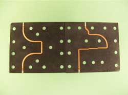
Fig. 8 Single-single section and single-triple section tandem-coupler center boards.
Two dual band tandem-couplers were built and tested, single-single (identical coupling) and single-triple section type. Three RO5880 dielectric boards compressed inside the housing formed a three-layer structure with coupled and interface striplines located on both sides of the center board, forming so-called “through the board coupling.” Such a design approach delivers excellent electrical performance, particularly for the return loss, necessary coupling and assures high power operation capabilities. Figure 8 shows a top view of both single- and triple-section based tandem coupler center boards.
It should be mentioned that a thorough 2.5D EM simulation preceded the experimental prototype development. Figures 9 and 10 show the coupling responses for single – single and single-triple section tandem-coupler prototypes with lower and upper operation bands centered around 2.38 and 7.14 GHz (3 times frequency), respectively.
Fig. 9 Coupling and return loss of single-single section tandem coupler
Fig. 10 Coupling response of single-triple section tandem-coupler
In the first case, the MAR region of better than 0.3 dB was observed over approximately 100 MHz widebands around the crossover points, with phase shift of 89.7° to 91.7°, measured between ports over the entire frequency span. In the second case (single-triple section), the axial ratio below 0.45 and 0.37 dB were maintained over 1 GHz and 600 MHz widebands for the upper and lower operating bands, correspondingly. The actual insertion loss, different for single- and triple-section component couplers and varying with the frequency, contributed to the asymmetry of the actual prototype responses in the lower and upper MAR regions.
Conclusion
In this article, dual-band hybrid-couplers were described and developed for the circularly polarized signal formation. The couplers are formed by cascading two rather simple component hybrids, which deliver nearly perfect power split and necessary phase shift (about 90°) between two output ports at the bands of MAR located at the frequencies different by factor 3 or greater. The simplicity of the design and flexibility of MAR location adjustment, as well as rather low axial ratio achieved for both frequency bands of interest, makes this approach much more appropriate than traditional (ultra broadband) multistage coupler, especially when the low axial ratio and insertion loss are required only for two frequency separated bands.
References
1. E.G. Cristal and L. Young, “Theory and Tables of Optimum Symmetrical TEM-Mode Coupled-Transmission-Line Directional Couplers,” IEEE Transactions on MTT, Vol. 13, No. 5, September 1965.
2. J.P. Shelton and J.A. Mosko “Synthesis and Design of Wide-Band Equal-Ripple TEM Directional Couplers and Fixed Phase Shifters” IEEE Transactions on MTT, Vol. 14, No. 10, October 1966.
3. Harlan Howe, Jr. “Stripline Circuit Design,” Artech House Inc., 1974.
4. David M. Pozar “Microwave Engineering”, Addison-Wesley Publishing Co. Inc., 1993.