
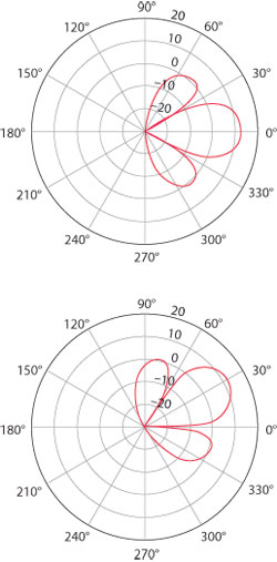
Figure 1 Lobes created by simple beam steering.
Recently, both wireless and business media have cast a spotlight on TD-LTE. At a conceptual level, TD-LTE is easily understood. It is simply LTE with uplink and downlink multiplexed in the time domain rather than the frequency domain. The result is an LTE system that can be realized in a single frequency band as opposed to the paired bands required in FDD-based LTE. The most immediate and obvious consequence of TD-LTE is that LTE can be deployed by operators who do not own paired frequency bands. To be more specific, it gives WiMAX and TD-SCDMA licensees a path to LTE deployment.
Just as TD-LTE solves a problem for many operators, another wireless innovation solves a separate problem for the entire industry: Multiple-Input Multiple-Output (MIMO) antenna techniques offer faster data rates and better system capacity, without expending resources in the time or frequency domains. In an m×n MIMO system (one using m transmitting antenna elements and n receiving antenna elements), the theoretical maximum data rates are limited by the smaller of {m, n}. However, larger numbers of transmitting elements can improve system coverage and quality by improving system SNR, leading to growth in the study of 8×n MIMO systems, where each base station is equipped with eight antenna elements.
None of this is a surprise to Microwave Journal readers, but the marriage of multiple antenna techniques and time-domain based uplink/downlink multiplexing results in an interesting and useful attribute: since the uplink and downlink share a single frequency band, uplink channel estimation can be used to make reasonable assumptions regarding downlink channel characteristics. The TD-LTE uplink and downlink are said to be “characteristically identical”.
This channel reciprocity leads to a way to improve both coverage and system quality: MIMO beamforming. While MIMO beamforming is not specific to TD-LTE, channel reciprocity in a single uplink/downlink frequency provides advantages that make beamforming attractive in TD-LTE deployments.
Beamforming Fundamentals
The term “beamforming” is sometimes used without qualification, which can cause confusion. Technically, beamforming can be as simple as beam steering, where two or more antennas radiate the same signal with controlled delays or phase shifts creating directed lobes of constructive interference (see Figure 1).
The beamforming used in TD-LTE systems is a somewhat more complex proposition, in part because of the mobile nature of terminal devices. A technique called Eigen beamforming uses information about the RF channel to statistically weight amplitude and phase parameters of the transmitting antenna elements. While Eigen beamforming is not the most calculation-intensive type of beamforming (a method called Maximum Ratio Transmission performs the same types of weighting but on a per-subcarrier basis), the fact that it is being used in high-element count 8×n MIMO systems makes it a challenging proposition, both in the implementation and verification stages of system development.
TD-LTE and 8×n MIMO
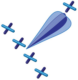
Figure 2 An 8 × 2 beamforming system creates orthogonally polarized beams.
Most planned TD-LTE deployments are designed around transmitting antennas with eight antenna elements. In these systems, four antenna elements, separated by distance, are physically oriented at one angle. Another four elements are located so that each is concentric with one of the first four, and each of these latter four is oriented at a right angle to its partner element, as shown in Figure 2.
Each group of four similarly oriented elements forms a beam that can be aimed in a specific direction. Correlation between these four radio links is purposely high. The two orthogonally polarized beams exhibit low correlation with each other, acting somewhat like a 2×n MIMO system and therefore able to transmit multiple layers or data streams. The system therefore implements the data-rate maximizing benefits of a MIMO system, while taking advantage of beamforming to optimize signal strength in specific directions. This is commonly known as a dual-layer beamforming system, where each layer can represent a separate stream of data.
A dual-layer MIMO beamforming system can be used as either a single-user MIMO system (SU-MIMO), where both data streams are assigned to a single user equipment (UE), or a multi-user (MU-MIMO) system, where each stream is assigned to a separate UE. This provides tremendous flexibility to the network operator, who can choose to deploy such a system, either to maximize coverage or to maximize per-user data throughput.
How Beamforming Works
In any beamforming system, it is required that the system can estimate the direction of the targeted UE. In FDD systems, this is a function of feedback from the UE in the form of the Precoding Matrix Indicator (PMI), but once again, the channel reciprocity of TD-LTE eliminates this requirement. Instead, the UE sends a channel-sounding signal to the base station. The base station then estimates the UE’s direction of arrival (DoA) by examining the relative phase difference between the co-polarized antennas. Note that while this estimation is done in the uplink, the base station uses channel reciprocity and can transmit in the downlink based on the estimation of the uplink.
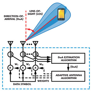
Figure 3 Adaptive beamforming system.
Next, based on the estimated DoA, the base station dynamically adjusts the “antenna weight” (relative amplitude and phase) of each element of the antenna array so as to steer the beams towards desired users, and/or to steer nulls in the direction of sources of unwanted interference. Figure 3 shows the basic concept.
The above scenario is actually simple beam steering. Eigen beamforming adds some intelligent processing, but the desired fundamental effect is the same: the system estimates downlink channel parameters by taking advantage of reciprocity and adjusts antenna weights accordingly.
Testing Beamforming
Many of the challenges to creating realistic MIMO test beds in the lab have previously been identified and resolved. Because of the spatial nature of both beams and MIMO link components, lab-based testing must implement both proper polarization and realistic antenna patterns in order to create an effective testing environment.
TD-LTE adds a requirement beyond those used in simple MIMO testing: the uplink and downlink must be reciprocal in terms of fading as well as all transfer function characteristics. In the testing lab, this is not as straightforward as it may seem. Modern channel emulators are, by necessity, made up of unidirectional RF channels. Accurately emulating reciprocal channels requires a great deal of care in producing synchronized, accurately duplicated fading. A channel emulator that works very well for most testing may not be a good match for TD-LTE testing if it cannot produce nearly identical channel conditions in the uplink and downlink.
Another critical area of concern is phase accuracy and calibration. This seemingly arcane topic has generated a lot of work in recent months, leading to new advances in state-of-the-art lab-based RF channel emulation. In practice, phase alignment is affected by:
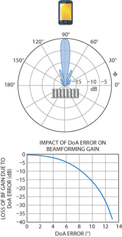
Figure 4 Phase error and its impact on beamforming gain (eight-antenna linear array).
- adjusting the channel power level
- adjusting the signal to noise ratio
- changing channel models
- adjusting frequency
- power cycling
While SISO and non-beamforming MIMO systems are relatively insensitive to the slight phase shifts caused by these procedures, MIMO beamforming is especially susceptible to phase-related inaccuracies. Figure 4 shows a radiation pattern of a typical eight-antenna uniform linear array with DoA degrees of error. An error of eight degrees results in 10 dB loss of beamforming gain; an error of 14 degrees will cause loss of the link.
Accurately testing MIMO beamforming therefore requires periodic phase calibration of the system. While it is possible to manually phase-calibrate a channel emulation system used for testing MIMO beamforming, the user can easily spend 5 to 8× more time calibrating than doing the testing. Even more importantly, manual phase-calibration requires the disconnection and re-connection of multiple RF connectors, which has an effect on long-term system stability.
The solution is automated phase calibration, which joins dynamic environments and geometric channel models as “must have” capabilities in modern channel emulators. Driven largely by fundamental research involving prototype 8×n MIMO beamforming systems, advanced channel emulation systems now offer automated phase calibration requiring no manual intervention. In an automatically phase-calibrated system, a quick button-push or mouse click fine-tunes the phase accuracy of each radio link used by the system without cable disconnection, and most importantly, ensures the validity and accuracy of test results.
conclusion
As TD-LTE attracts more attention (ABI Research recently estimated that half a million base stations will be deployed by 2016), new challenges become apparent, particularly in testing. Eight-antenna MIMO beamforming is a unique feature exploited by TD-LTE to offer both multiple layers and the directional aspects of beamforming.
In this article, the basic concept of TD-LTE was introduced and how MIMO beamforming works was explained. An analysis of error in testing beamforming was discussed and the single most critical test challenge (phase-related accuracy in the test bed) was identified. Finally, the article explored an effective solution to this challenge.