
 | |||
Powerfully flexible software models are now available for surface-mount (SMT) resistor, inductor and capacitor (RLC) components that are accurate over wide ranges of frequency, part value and mounting configurations. These unique, substrate-scalable Global Models™ are developed from careful measurements taken in typical application circuit mounts on multiple boards. Global Models account for the complex interactions between the board, ground planes, solder pads and the component. The models, formatted for use in electronic design automation (EDA) software such as Agilent ADS,™ Ansoft Designer,™ Applied Wave Research Microwave Office™ and Eagleware Genesys,™ are generally valid through the first two higher order resonances of the parts, and are scalable over wide ranges of substrate properties and part values (for example, 1 to 100 nH inductance, 0.5 pF to 10 µF capacitance, or 10 to 120 kΩ resistance).1 The Modelithics CLR Library™ contains over 40 well-documented Global Models, representing literally thousands of components, and delivers unparalleled ease of use and design speed.
Commonly overlooked, the presence of substrate-dependent parasitic effects in the frequency response of SMT components typically becomes evident above a few to several hundred megahertz. These effects are attributable to the physical size of the component and are described by parameters such as the effective series inductance (ESL) and effective series resistance (ESR). In addition to the intrinsic component characteristics, there can be significant extrinsic effects that are related to the circuit environment in which the part is mounted. An accurate model of an SMT RLC component must account for both intrinsic and extrinsic parasitics through suitable equivalent circuit parameters. The models should be capable of scaling all circuit parameters with changes in the substrate height and dielectric constant to increase the versatility of the model. The models should remain valid through multiple harmonics of the design frequency, particularly when used to represent bias or matching elements in nonlinear circuit simulations.
In addition, models that scale all equivalent circuit parameters with the nominal component value can play an important role in improving the efficiency of the design process. Such models allow a designer to incorporate true component performance from the outset, and eliminate the need to successively substitute individual models (or S-parameter data sets) as a design matures.
Modelithics Global Models are a significant improvement over the more widely available RLC models built into EDA software or downloadable from vendor Web sites that typically model only up to the first self-resonance of the part, and are developed from S-parameter data taken in a generic test fixture. In many cases only the S-parameter data is provided. This introduces the potential for larger errors to occur if the user unknowingly simulates outside the measured range. Global Models enable new design paradigms in the areas of optimizing part-value selection and statistical simulations, and enable first-pass success for hybrid board designs. As seen in Figure 1, the inputs to a Global Model are the nominal part value and the substrate parameters, any or all of which can be defined to be statistical variables.
 | ||
| Fig. 1 Modelithics Global Model in ADS. | ||
The model extraction process uses multiple measurement data sets as input, including precise ESR measurements. The result is models that remain well behaved under extrapolation, both to DC and to very high frequencies, on a wide range of PCB configurations.
Accounting for Substrate Effects
When an SMT component is attached to its printed circuit board environment, it immediately becomes part of a coupled electrical network that includes the interconnect pad stacks, the ground plane and the part itself. There is an unavoidable part-to-ground plane capacitance that is dependent upon the substrate height and dielectric constant, the footprint of the part, and the physical structure of the part. A multi-layer capacitor, for example, can be considered a complex, strip-like transmission line with the PCB back-plane serving as its ground, and thus modeled using the familiar L-C equivalent circuit model commonly used for transmission lines. As the substrate height and/or part thickness decrease, a corresponding increase in the parasitic capacitance to ground occurs. In contrast, the effective series inductance of a chip capacitor will decrease as the part nears the ground plane, as happens to the inductance of all two-wire transmission lines when the conductors are brought together. Chip resistors and inductors naturally exhibit similar characteristics.
The substrate-dependent parasitic parameters can have a significant impact on the frequency response of a component, particularly as PCB designs continue to migrate to smaller board thickness. Figure 2 illustrates the measured S-parameters of a 10 nH 0805-style inductor mounted in a series configuration on different FR4 substrates. The frequency of the parallel resonance on the 14 mil FR4 is about 2 GHz higher than for the 59 mil case. Substrate effects are evident even in the low frequency range (2 to 3 GHz), as indicated by the S11 data in the inset.
 | ||
| Fig. 2 Measured (blue) and modeled (red) data for a 10 nH 0805 inductor on 14, 31 and 59-mil FR4 (vendor data shown in black); S11 phase shown only for 31-mil FR4. | ||
The Smith chart in Figure 3 demonstrates the versatility of global, substrate-dependent models. The input impedance of series-mounted resistors (0 to 10 kΩ), inductors (10 to 4700 nH) and capacitors (1 to 1800 pF) is shown at 2.5 GHz. The display contrasts ideal element values (circles) with the predicted responses of three Global Models (one each for the resistors, inductors and capacitors) mounted on four FR4 substrate thicknesses (5, 14, 31 and 59 mils). The performance on each board is dramatically different than ideal component behavior, and differs from board-to-board. Here the value of a single R, L or C model that can track the wide variation in frequency response is self-evident. The increasing effects as board thickness decreases can be clearly seen.
 | ||
| Fig. 3 Input impedance for series mounted inductor (blue), resistor (red) and capacitor (green) families simulated on different substrates at 2.5 GHz and compared to ideal performance (circles). | ||
An example simulation in Eagleware Genesys is shown in Figure 4. Shown is a substrate sweep for a 4.7 pF chip capacitor. The self-resonance frequency changes nearly 7 GHz over the 5 to 62 mil substrate variation.
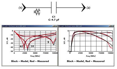 | ||
| Fig. 4 Measured data to model comparison in Eagleware’s Genesys for a 4.7 pF capacitor on 5, 31 and 62 mil FR4. | ||
Parts Value Scaling — One Model Fits All
Component models that scale with the nominal part value (“Global Models”) can be indispensable to the microwave circuit design process. While the accuracy of a substrate-dependent parasitic model is key to the simulation process, the results presented in the previous section highlight the non-ideality of typical SMT components above several hundred megahertz. One effect of the non-ideality is that, more often than not, the optimum part value in a given application is best determined via iteration after the first-pass design is completed. Even in a schematic with a small number of components, manual substitution of individual models is very tedious, and increases geometrically with parts-count. Figure 5 illustrates how the part-value scalability of Modelithics Global Models enables the use of automated circuit optimization techniques to greatly improve the overall efficiency of the design process.
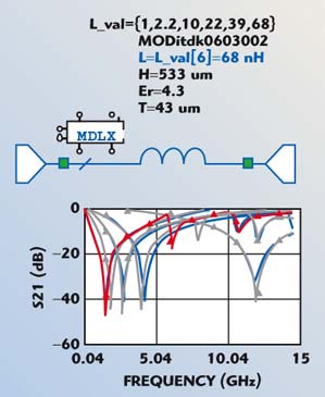 | ||
| Fig. 5 Microwave Office setup and results for discrete optimization of an 0603 inductor Global Model (measured data shown in blue). | ||
The final example, shown in Figure 6, demonstrates the accuracy attainable for substrate effect prediction for circuits containing multiple SMT components, such as the bandpass filter shown, as well as the ability to simulate variations in circuit performance due to either part-value tolerances, substrate tolerances, or both.
 | ||
| Fig. 6 Bandpass filter example in ADS showing the same components simulated and measured on 40 mil and 5 mil FR4 (a and b) and statistical simulation of effects of part value (c) and substrate thickness (d) tolerances on 5 mil FR4. | ||
Modelithics Inc.,
Tampa, FL (813) 866-6335, www.modelithics.com.