
Radio frequency identification (RFID) has become and will continue to be very important in the area of automated identification. With the current emerging RFID technology, it is now possible to have an under-the-skin ATM/credit card or to pay up for a trolley full of goods by pushing across an electronic sensor without unloading them on the counter. Now, retailers such as Wal-Mart, Target, Tesco, Metro and Albertson’s are the leading companies in adopting RFID in the retail supply chain. Gillette, Delta Airlines, Prada, Marks & Spencer and dozens of other Fortune 5000 international organizations and major corporations are supporting large-scale pilot projects, deploying RFID technology to support a wide variety of applications within the supply chain and beyond. According to a survey conducted by IBM, the primary initial objective of retailers deploying RFID systems would be to better manage inventories, out-of-stock products and warehouse efficiency. Many retailers are also interested in testing RFID for theft prevention purposes, while manufacturing companies are also examining the transportation and logistics implications of the new technology. Other than applications in the retail markets, terrorist and privacy concern after September 11th urged the US to adopt RFID in passports.3 The RFID chip embedded in the passport will make them more secure, and ensure that the bearer is the person who was issued the passport originally. When queried, the chip will deliver the name, address, date and place of birth of the bearer, along with a digital photograph. The information will not be encrypted, but will contain a digital signature certifying the authenticity of the chip. This technology does not work well over long distances, and the readers required for the type of chip chosen for the passports would be fairly difficult to hide, thus making it almost impossible to envision terrorists tracking US citizens as they emerge from customs.
This article first provides an overview of RFID systems and how they work, followed by the history of RFID, a review of recent and future RFID systems, and finally some recommendations for future work in this exciting technology.
Time Line of RFID
The combination of radio broadcast technology and radar are associated with the technology lying behind RFID. In 1906, Ernst F.W. Alexanderson first demonstrated continuous wave (CW) radio generation and transmission of radio signals and radar was introduced in 1922.4 Following the convergence of these two important radio disciplines, RFID was invented in 1948 by Harry Stockman and described in his first paper.5
However, the first obvious use of RFID technology can be traced to the British during World War II. Tags were placed on British allies aircraft to distinguish between their own aircrafts returning to base and enemy aircrafts who were invading. The tag produced a signal as the allied aircraft approached the base and if the base received no signal, the aircraft would be known as a ‘foe,’ meaning that enemy aircraft were approaching. This system was called ‘Identify: Friend or Foe’ (IFF). A variation of the system is still used today for aviation traffic control.6
After the first breakthrough of RFID, in the 1950s, the technology never really picked up until the 1960s to the 1980s. The 1960s saw the development of the theory of RFID and the start of its commercial applications. Commercial companies such as Sensormatic, Checkpoint and Knogo developed Electronic Article Surveillance (EAS) equipment to counter theft. EAS is arguably the first and most widespread commercial use of RFID. These types of systems are ‘1-bit’ inexpensive tags, whereby only the presence or absence of a tag could be detected. At that time, the systems used either microwave or inductive technology.4 In the late 1960s and early 1970s, RFID was used to track nuclear materials in response to the need for more security and safety surrounding their use.6 Developmental work on the RFID tagging of equipment and personnel continued to increase in the 1970s. Applications were intended for animal tracking, vehicle tracking and factory automation. Mario Cardullo7 received the first patent for a passive, read-write RFID tag from the US Patent Office on January 23, 1973. He got the idea for the tag in 1969 after witnessing the flaws in the CARTRAK optical system, an optical reflector system, for the railroad industry. Notable advances in this technology were also being realized at research laboratories and academic institutions such as Los Alamos Scientific Laboratory, Northwestern University and the Microwave Institute Foundation in Sweden. Two companies, Amtech and Identronix Research, started to explore commercial uses of RFID for animal tracking.6 RFID tags were placed in the backs of dairy cows to allow tracking of the animals’ identifications and temperatures. Furthermore, automatic feeding without overfeeding could be accomplished when the animal’s unique ID code was obtained from the tag. Railroad companies became interested in RFID after bar code technology failed to successfully track rolling cars in the dirty and unpredictable outdoor environment.
Most of the early RFID research used 900 and 900/1800 MHz frequencies. By 1983, low frequency (LF), medium frequency (MF), very high frequency (VHF), ultra high frequency (UHF) and microwave frequencies were also being utilized.6 The 1980s became the decade for full implementation of RFID technology.4 RFID tags were regularly being manufactured by several US and European companies. In 1988, the primary effort in RFID shifted somewhat from new applications to performance improvement, cost reduction and size reduction.
The 1990s were a significant decade for RFID since it saw the wide scale deployment of RFID.4 This is also the era when questions on standards emerged. A new effort underway was the development of the Texas Instruments Registration and Identification System (TIRIS), used in many automobiles for control of the starting of the vehicle engine. The TIRIS system and others, such as from Mikron — now a part of Philips — developed new uses for dispensing fuel, gaming chips, ski passes, vehicle access and many other applications.
Additional companies in Europe were becoming active in the RFID race as well, including Microdesign, CGA, Alcatel, Bosch and the Philips spin-offs of Combitech, Baumer and Tagmaster. A pan-European standard was needed for tolling applications in Europe, and many of these companies were at work on the CEN (Comité Européen de Normalisation) standard for electronic tolling. Tolling and rail applications were also appearing in many countries, including Australia, China, Hong Kong, Philippines, Argentina, Brazil, Mexico, Canada, Japan, Malaysia, Singapore, Thailand, South Korea, South Africa and several European countries.4
Advancement in RFID System Design
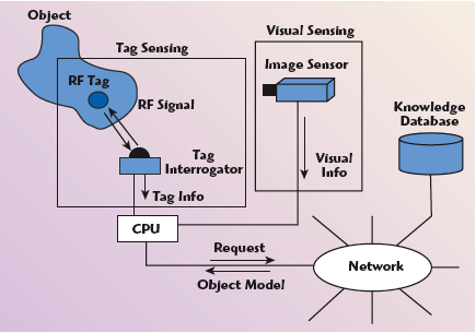
This section highlights the most up to date development of RFID systems, produced using the most advanced RF technologies available to date. In 2002, M. Boukraa and S. Ando presented a paper on a machine vision system that uses the RFID tag to identify objects prior to locating them visually.8 The system is developed for a desktop PC driving the reader and the image sensor (a camera) and is connected to a PC server that manages the object model database. By using the RFID tag to assist in the 3D scene analysis, the central processing unit (CPU) commands the RFID system and retrieves information such as the object’s tag ID from the network. The retrieval of a complete model of the detected object is done through a network knowledge database, designed in XML. Tag sensing and visual sensing are then integrated to perform a high level vision task. The shape of the object is stored as 3D homogenous coordinates. Figure 1 shows the general architecture of the system. Generally, the tag-based vision algorithm falls into four main parts: reads tag info and retrieves object model from database; detects lines and edges with Hough transform; extracts a discriminating six-point subset from those featured points; and calibrates the camera and registers the object. This system makes it possible to simplify any object recognition task to a problem of registering the object model to the image. The recognition part is independent of the number of models in the database.

In early 2003, Michelin, the tire maker, adopted the RFID system to track expired and worn out tires, following the enactment of the Transportation Recall Enhancement, Accountability and Documentation (TREAD) Act by the US Congress in 2000. With this system, an RFID tag is embedded in the tires,9 enabling them to be tracked electronically. Figure 2 shows the Michelin’s RFID tag. The microchip in the tag holds a unique ID for the tire, which can be associated with the vehicle identification number. The chip can store information about when and where the tire was made, its maximum inflation pressure and size. Information can be updated with a handheld reader. Although other tire makers have demonstrated the ability to read RFID tags embedded in tires, Michelin claims to be the first to meet the Automotive Industry Action Group’s B-11 standard for North America, which calls for a read distance of 24 inches. Achieving that range has been a challenge because the rubber makes it harder to read the tag. Michelin took microchips from Fairchild Semiconductor and Philips Semiconductor and designed its own special antenna to boost the read range. The antenna was designed to compensate for the fact that electromagnetic waves travel differently through rubber than through air. The tag that Michelin designed loses only 10 percent of its read range when it is embedded in a tire. The other key issue was to ensure that the rubber bonds carefully to the antenna so that the antenna, which is made of wire, does not break or is dislocated. In order to protect the antenna and to ensure the firmness of the tag in the tire, Michelin developed a proprietary coating to put on the tags before embedding them into the rubber. Besides basic tracking of the tires, the RFID system is also being adopted as pressure and temperature sensors for the tires. These sensors,9 developed independently by Philips and Texas Instruments, use active tags to measure the vehicle’s tire pressure and temperature. Readers are then placed on the dashboard of the vehicle to broadcast the readings to the user. Philips produced such a tag known as a “signal conditioning chip,” or P2SC.10 At regular intervals, the chip will broadcast the temperature and pressure of each tire, either through a warning light or digital readout, displayed on the dashboard. The P2SC chip can withstand shock resistance up to 2000G and temperatures of up to 175°C. The system is designed to work with the receivers used for remote keyless entry. Antennas are installed in each wheel well. The keyless remote entry receiver, which uses rolling ID numbers to match keys to cars, is modified so that it can send out a low frequency signal through the wheel well antennas. The low frequency signal activates the RFID tag either in the tire valve or inside the rim of the tire. The activated tag will then broadcast its rolling ID number at either 315 or 434 MHz, which identifies the tire and its location, as well as data on the temperature and pressure of that tire. Philips does not make the entire active sensor but produces the microchip that will communicate with the wireless remote entry receiver. A system integrator would combine the chip with a pressure and heat sensor made by a third party. The two chips would likely be mounted on a tiny circuit board with a small battery.
Hitachi further worked on its ?-Chip11 and developed a new version of the ?-Chip by embedding an antenna into the chip.12 It was announced on September 2, 2003. The new chip cut the cost of the previous tag in half.13 This newly developed version features an internal antenna, enabling chips to employ the energy of the incoming electromagnetic waves to wirelessly transmit its ID number to a reader. The 0.4 × 0.4 mm chip can thus operate entirely on its own without the need of external antennas. The internal antenna is formed using a bump-metalization technology (used to create the electrical contacts of an IC), a process already widely used by semiconductor manufacturers, thus eliminating any need for specialized equipment. The new ?-Chip can be easily embedded in most paper sheets such as bank notes, gift certificates, important documents and business forms, which require a highly sophisticated level of security to prevent counterfeiting and to help in the automation of logistics systems and other business processes. For these purposes, the ?-Chip was used to identify and validate entrance tickets to Expo 2005, held in Aichi, Japan, in March 2005. Other potential application includes embedding them in agricultural products to ensure the safety of food by providing trace detection of ingredients.
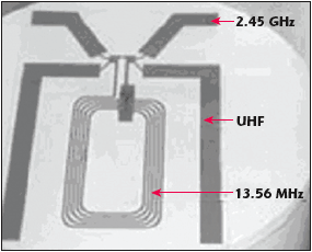
The multi-frequency MM chip14 by Toppan Forms and FEC Inc. is following the trend. Designed in March 2004, the antenna is affixed to the chip to form the tag, as shown in Figure 3. This tag can be read from 2 to 3 mm at a frequency of 2.45 GHz. Additionally, a small “booster antenna” can be added to increase the read distance to 24 to 30 cm and another external antenna can extend the range to about 50 cm. At a frequency of 13.56 MHz, the reading distance ranges from 15 to 20 cm with the booster antenna and from 30 to 40 cm with the external antenna. In the UHF spectrum, the tag can be read up to 1 meter with the booster antenna and up to 5 meters with the external antenna. As such, in order to achieve the maximum read distances at the three common RFID frequencies (13.56 MHz, 868 to 956 MHz and 2.45 GHz), the chip needs to have an on-chip antenna and two other external antennas attached. Each antenna is tuned to work in a frequency range. As mentioned earlier, the tag can be read by Toppan’s special reader. Applications using the antenna-embedded MM chip include tagging airline baggage and goods in the supply chain.
A new automobile immobilizer system using three RFID readers15 has been developed making it three-times harder for prospective thieves to start a car’s engine. This new system, named TheftStopper1, was developed and manufactured in January 2005 by C-Chip Technologies, a Montreal security systems provider. TheftStopper1’s three RFID readers each have a nanowatt microcontroller and relay. One of the RFID readers serves as the starter cutoff or ‘mother’ unit, which controls the power to the two other control units. The other two units function as power switches and are installed at different parts of the car, such as the fuel pump, ignition circuit, computer or transmission relay. A car will not start unless all three-control units receive a signal from a key fob containing the correct ID code. As the key fob’s active tag can transmit its signal over a distance of 20 feet, the mother unit can communicate with the key fob, well before the driver even starts the vehicle, to verify whether the key fob’s ID code matches the one programmed in the mother unit. When the driver turns the ignition switch, a second connection is made between the mother unit and the two other units and the engine starts. Without the key fob’s tag, none of the three cut-off switches will allow electric current to flow to their respective devices.
The new RFID systems find an increasingly important role in automobile applications. The pressure, temperature tracking of the automobile tires and automobile immobilizer system confirmed this. Furthermore, the introduction of embedded RFID tags is finding applications in important documents, passports and currencies to avoid fraud and to preserve its authenticity. Advanced RF technologies play vital roles in this development.
Potential Future Implementations
This section highlights the use of advanced RF technologies in future implementations of the RFID system, which are being investigated by several companies.
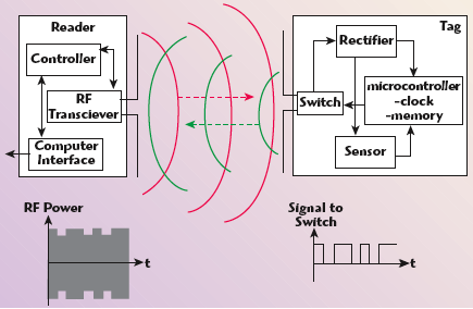
In 2003, S. Nambi, S. Nyalamadugu and M. Stuart of Auburn University started a project that uses RFID technology, integrated with sensors for detection of pathogens in food.16 The idea is to keep track of food products from initial production throughout the supply chain thus significantly reducing mortality rate and lost productivity due to food borne bacteria and pathogens like Salmonella and E. Coli. The frequency used is 13.56 MHz. In the initial stages of the project, a passive tag with reduced functionality and merely for detection of temperature was designed. Besides that, a very basic reader with a reading range of 10 cm was built for the system. The antennas for the reader and the tag are multi-turn rectangular loop antennas designed for a resonant frequency of 13.56 MHz, which were modeled using Numerical Electromagnetic Code (NEC) Windows Professional software. The biosensor is to be interfaced to the tag circuit using the microcontroller. The device will use a generic microcontroller with an on-chip memory and also input and output ports. The microcontroller can be software programmed to output a certain bit stream depending on the input that it will receive from the sensor. The program logic can poll the respective ports and detect changes in the input from the sensor. The biosensor will have sensitive biological film coatings that will change their material properties when in contact with the targeted pathogens. Figure 4 shows the pilot RFID biosensor system. When the reader activates the tag, it will start transmitting its identity code for a specific period of time. At the same time, a controller in the reader will decode the identity of the tag. While the tag is sending out the information bits, the sensor in the tag will alarm the microcontroller if a set temperature value is exceeded. The controller will then process the information and send a code, which is appropriate for that particular state of the system.
Another innovative implementation of the RFID system can be seen when two companies, Winwatch and Hitachi, teamed up to produce a new RFID product in which an Hitachi m-Chip is embedded in watches with an antenna to track and authenticate them and avoid counterfeiting. Winwatch is talking Swiss watch companies into employing this RFID system in the near future.
In July 2004, a Swiss company planned to adopt the RFID system in their range of watches to protect them against counterfeiting and to improve consumer services. As Swiss brands such as Cartier, Longines, Piaget and Rolex are often counterfeited, the Swiss company has already patented a way of embedding a tiny RFID tag in the glass crystal of a watch.17 With the teaming up of Winwatch and Hitachi Europe, Hitachi’s ?-Chip with its embedded antenna12 will be used to track the watches. Each ?-Chip contains a unique serial number that can be associated with a particular watch. When that watch is shipped to a retailer, the retailer can check the authenticity of the watch by checking the serial number with the watch’s manufacturer. The numbering system that uses Hitachi’s ?-Chip is proprietary. Therefore, companies wanting to use Winwatch’s technology for such applications would need to adopt the same proprietary system. Because of the small size of its antenna, the RFID tag can be read only if it is no more than 1 mm from the antenna of the RFID reader. By putting the chip in the watch crystal, tags can be added to the already-manufactured watches, and it is easier to read the tag in the crystal because there is no interference from metal or the body of the person wearing the watch. Winwatch is targeting more Swiss watch companies to employ this RFID system in the near future. Soon, the first interactive Swiss-made wristwatches with RFID tags embedded in the watch glass will be realized. Once implemented in this real retailer market, researchers can look forward to producing watches employing a RFID system that can replace current RFID cards for identification, access control and as a smart card.
So far, RFID systems have been used in pressure and temperature measurements of tires. In yet another breakthrough, Intel plan to adopt RFID in sensor networks to detect heat, light, movement and other environmental factors.18 Also known as motes, the sensors gather data and transmit it from one node of a network to another, until it reaches a node connected to a computer that can store and analyze the data. Unlike conventional computers, where people have to input most of the data and receive most of the computer’s output, this new sensor network will anticipate people’s needs and act on their behalf. The widespread deployment of RFID technology is expected to lead to the installation of more robust networks that can cope with the quantity of data that a sensor can generate. RFID tags with integrated temperature sensors are already on the market, and researchers are working on other low cost sensors that can be integrated with RFID tags.
Conclusion
The past three years have been important in the evolution of RFID technology. In 2003, RFID made major strides towards becoming a technology that can be used in open supply chains.19 However, there is still a lot of work to be done by the Auto-ID Center and the International Organization for Standardization (ISO) to finalize standards. The Electronic Product Code (EPC) has progressed to the point that Wal-Mart, the world’s largest retailer, is committed to using it. The Auto-ID Center has handed its research work off to the Auto-ID Labs, which are continuing to do important work. The Cambridge Laboratory, for instance, is working on concepts that could change the way goods are manufactured. The center handed the promotion of the EPC Network to EPCglobal, a joint venture between the Uniform Code Council (UCC) and European Article Number (EAN) International. EPCglobal is set-up to oversee the rollout of RFID standards worldwide.
In 2004, some 60 RFID vendors agreed to support one global protocol, EPCglobal Generation 2 protocol.20 End users have found ways to tag many difficult products so that they can be read reliably when they reach a retailer’s warehouse or store. Hardware products are improving at a rapid clip, and software companies are developing new middleware products and applications that can take advantage of real-time data. An infrastructure is being put in place to enable companies to make enough tags, labels and readers to meet demand.
References
1. F. Mohd-Yasin, M.K. Khaw and M.B.I. Raez, “Radio Frequency Identification: Evolution of Reader and Antenna Design,” Microwave Journal®, Vol. 49, No. 5, May 2006, pp. 242–254.
2. F. Mohd-Yasin, M.K. Khaw and M.B.I. Raez, “Radio Frequency Identification: Evolution of Transponder Circuit Design,” Microwave Journal®, Vol. 49, No. 6, June 2006, pp. 56–70.
3. “New Energy-efficient RFID Tag,” RFID News, RFID Journal (online), December 30, 2003, http://www.rfidjournal.com/article/articleview/718/1/1.
4. “Shrouds of Time: The History of RFID,” Document Version: 1.0, Publisher: AIM Inc., October 1, 2001, http://www.aimglobal.org/technologies/rfid/resources/shrouds_of_time.pdf.
5. H. Stockman, “Communication by Means of Reflected Power,” Proceedings of the IRE, October 1948, pp. 1196–1204.
6. Jim Eagleson, “RFID: The Early Years, 1980–1990,” Technical links, http://members.surfbest.net/eaglesnest/rfidhist.htm.
7. “Genesis of a Versatile RFID Tag,” Opinion, RFID Journal (online), http://www.rfidjournal.com/article/articleview/392/1/2.
8. M. Boukraa and S. Ando, “Tag-based Vision: Assisting 3D Scene Analysis with Radio Frequency Tags,” Proceedings of the Fifth International Conference on Information Fusion, Vol. 1, 2002, pp. 412–418.

Faisal Mohd-Yasin
9. “Michelin Embeds RFID Tags in Tires,” RFID News, RFID Journal (online), January 17, 2003, http://www.rfidjournal.com/article/articleview/269/1/1/.
10. “RFID Chip To Monitor Tire Pressure,” RFID News, RFID Journal (online), October 17, 2002, http://www.rfidjournal.com/article/view/93/1/1/.
11. “World’s Smallest RFID IC, the ?-Chip,” Hitachi Ltd., June 28, 2001, http://www.hitachi.com/New/cnews/E/2001/0628/.
12. “Hitachi Develops a New RFID with Embedded Antenna ?-Chip,” Hitachi Global, September 2, 2003, http://www.hitachi.com/New/cnews/030902.html.
13. J. Collins, “Hitachi Unveils Integrated RFID Tag,” RFID News, RFID Journal (online), September 4, 2003, http://www.rfidjournal.com/article/articleview/556/1/1.
14. “First Multi-frequency Chip Unveiled,” RFID News, RFID Journal (online), March 15, 2004, http://www.rfidjournal.com/article/articleview/831/1/1.

Mei Kum Khaw
15. C. Swedberg, “Triple RFID Protection for Cars,” RFID News, RFID Journal (online), January 3, 2005, http://www.rfidjournal.com/article/view/1304.
16. N. Subramanian, N. Sheshidher, M.W. Stuart and A.C. Bryan, “Radio Frequency Identification Sensors,” Proceedings of the 7th World Multiconference on Systemics, Cybernetics & Informatics, Orlando, FL, July 27–30, 2003.
17. “Startup Says It’s Time for RFID,” RFID News, RFID Journal (online), July 13, 2004, http://www.rfidjournal.com/article/articleview/1026/1/1.
18. M. Roberti, “RFID Ushering in Age of Sensors,” RFID News, RFID Journal (online), November 23, 2004, http://www.rfidjournal.com/article/articleview/1251/1/1/.
19. “SkyeRead H2,” SkyeTek RFID Engineering, http://www.skyetek.com/readers_ H2.html.
20. “The Two-sense RFID Reader,” Northern Apex Solutions Integrator, http://www.rfidread.com/pdf/tsr222.pdf.

Mamun Bin Ibne Reaz
Faisal Mohd-Yasin received his BSc and MSc degrees in electrical engineering from George Washington University, Washington, DC, in 1999 and 2001, respectively. He is currently a lecturer on the faculty of engineering, Multimedia University, Malaysia. His current research interests include mixed-signals and RFIC design, and MEMS.
Mei Kum Khaw received her BSc degree in computational physics and electronics from the University of Malaya, Kuala Lumpur, in 2003. She is currently pursuing her M.EngSc degree at Multimedia University, Malaysia. Her research interests include analog/digital VLSI design, RFID systems and ESD protection design.
Mamun Bin Ibne Reaz received his BSc and MSc degrees in applied physics and electronics from the University of Rajhashi, Bangladesh, in 1985 and 1986, respectively. Since 2001, he has been a lecturer on the faculty of engineering, Multimedia University, Malaysia, involved in teaching, research and industrial consultation. He is the author or co-author of more than 40 papers on design automation and IC design for bio-medical applications.