
Ask any engineer what is needed from an RF/microwave design tool and you will think you are stuck in a scene from Top Gun: “I feel the need for speed.” The thirst for greater simulation speed is never quenched, although model accuracy is just as important. Go across the aisle to the manager’s office and the tune is slightly different: time-to-market and reducing design spins and uncertainties are the top priorities. Keeping one step ahead of the competition means satisfying both product specifications and production schedule, while at the same time minimizing the manufacturing and engineering costs. What’s a state-of-the-art design facility to do?
Dramatically Improved Speed and Accuracy
The Microwave Office® 2004 design suite is specifically built to address the speed requirements of design engineers while reducing the uncertainty issue for management. On the speed and accuracy front, Microwave Office software delivers orders of magnitude improvement in nonlinear and electromagnetic (EM) analysis speed, as well as capacity improvements across the board. In addition, more nonlinear models have been included in this latest version of the software, enhancing model accuracy and providing even broader agreement between the time-domain and frequency-domain simulators. Addressing design flow, AWR literally brings EM analysis right into the design capture phase of the design. The software is integrated with more EM solvers and offers layout capacity for mask or reticule creation for microwave integrated circuit (MIC), module, low temperature co-fired ceramic (LTCC) and monolithic microwave integrated circuit (MMIC) designers or flow integration with Mentor Graphics design tools for printed circuit board (PCB) designers. The Microwave Office unified electro-physical data model enables a single database entry, such as a resistor, to instantly relate to all of its views, or representations, within the software and across integrated tools. The designers’ artistic side will love the three-dimensional (3D) graphs and graphically defined, multiple-coupled bondwire model.
Circuit Simulation
Harmonic balance (HB) is the heart and soul of microwave design. The Microwave Office 2004 harmonic balance engine has been enhanced in several areas. Devices that are not part of the signal path can be automatically detected and linearized allowing the HB engine to focus computational horsepower directly on the truly nonlinear device within the design. The result, shown in Figure 1, is a more than 100× performance improvement for complex microwave designs. For very large circuits or circuits containing an excessive number of harmonics, the performance improvement can be even more substantial.

Fig. 1 100Sx speed improvement for complex microwave designs.
Not only is the simulation speed faster, but also convergence is more robust and gives better access to results. The numerical stability of the solver and the nonlinear models has been improved to give increased robustness and configurability. The engine has a trainable solver that enables the designer to optimize its performance for different types of circuits (for example, mixers may require different settings than power amplifiers for optimal performance).
Nonlinear noise, oscillator analysis and phase noise have also been improved for speed and analysis. Engineers can now mix nonlinear and linear elements in linear noise analysis or measure noise vs. power. Oscillator start-up transients can be simulated and phase noise at any circuit node can be measured.
If transient analysis is a necessary part of the design flow, HSPICE®“ can be brought to bear directly from a single, frequency-domain-based schematic. Models accurate to 100+ GHz are created on the fly from lumped element, distributed element, or S-parameter file descriptions of the linear elements. Nonlinear models have been verified for compliance with HB results to guarantee consistency between the two simulation methods.
Industrial Strength EM
Running out of memory during EM analysis means disk-swapping and what seems like infinitely longer runtimes. AWR’s EMSight™ simulator now utilizes a new block matrix solver to expand capacity. The new solver eliminates memory limitations by dynamically resizing the submatrix to the available memory in the computer. The result is that there are no practical limits to the size of the problem that can be worked on within RAM. For example, with most EM tools a structure with 50,000 unknowns is virtually unsolvable due to a lack of memory; with the EMSight simulator, however, it can now be solved with 512 MB of RAM in about 24 hours per frequency point.
EM solvers for engineers are like power tools for a carpenter — the right one is needed to do the job correctly. The AWR EM Socket™ interface — either integrated into the Microwave Office design environment as a native solver or operating directly from the native AWR database — gives users access to one of the most popular gridded method-of-moments (MoM) products. Integrated in the Microwave Office 2003 with Sonnet Software’s EM product, the Microwave Office 2004 EM Socket interface is now ported to Zeland Software’s IE3D non-gridded MoM, MEM Research’s EM3DS full 3D spectral domain and OEA International’s NetAn RFIC parasitic extraction.
EM Optimization and Dynamic Structure Generation
Design flows often bog down when EM is brought into the picture because of the disconnect from the schematic. Individual elements in the schematic become blended and merged with each other to form the overall structure and it is difficult to separate or discern the effects of one piece of metal from another. Microwave Office 2004 software introduces dynamic EM model creation under the control of the schematic. Schematic elements are associated with single or multiple extraction controls and directly feed the EM structure under the control of the schematic, thereby enabling schematic-based optimization of EM structures. These dynamically-created EM structures, because of the single data model architecture, use the manual or automatic placement orientation data from the layout and can be resized and placed on the fly to the EM solver of choice.
Layout and User-interface Enhancements
Microwave Office 2004 layout capacity has been enhanced to handle millions of devices. Typically, this is not the case for a microwave design, but it does mean blazingly fast refresh times for circuits utilizing extreme degrees of hierarchy. Preparation for mask making for MMICs or modules is sped up considerably. Layout in the Microwave Office 2004 design suite also offers edit-in-place for hierarchical layouts so that lower levels of layout hierarchy can be modified relative to, rather than isolated from, their adjacent layout features.
Included in the Microwave Office 2004 software are many user-interface enhancements. Operating point annotations for nonlinear devices and annotations in general for any branch current or node voltage no longer need a corresponding meter element. Optimization goals can be copied more easily now by drag-and-drop from the project palette.
3D Graphs and Measurements
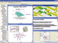
3D perspectives on layouts are not new to Microwave Office software, but for 2004 a new 3D graphing capability, shown in Figure 2, has been added to plot measurements vs. two independent parameters. There are extensive controls to adjust the 3D lighting source as well as the direct appearance of the graphed surface.

Fig. 2 3D graphics add another dimension to data analysis.
A moveable probe capability in the Microwave Office 2004 design suite provides designers with a measurable view into nearly any circuit node. The probe is picked up and dropped with a simple drag of the mouse and any associated measurements are instantly updated; no simulations need to be rerun. Furthermore, the probe is non-interfering and does not remove any power from the probed signal path. The moveable probe is also useful with the system simulator and can be used in conjunction with the new budget analysis capability in AWR’s Visual System Simulator™ 2004 (VSS) system design software.
Models
The Microwave Office 2004 design suite offers several new and updated models, plus a radically new approach for some devices which normally have been difficult to use. New bipolar models have been added (HICUM, Mextram 504 and VBIC 95P) for use with HB and MESFET favorites such as EEHEMT, Triquint Materka and Staatz, and are available with HSPICE. Among the other elements added are new suspended substrate models for microstrip and stripline configurations.
Many classes of parts have been traditionally difficult to use with graphical schematic capture systems because the part itself changes based on its parameter values. For example, the number of coupled lines in a coupled line element is sometimes itself a parameter, making it impossible to “put down” the needed model since no one symbol can represent all of the configurations needed. Another example of this is equation-based, or symbolically defined, voltage-controlled sources where the number of nodes is directly related to the number of controlling voltages and the number of parameters needs to vary based on the defining equation itself. Microwave Office 2004 software solves all of these problems with dynamically defined symbols. For coupled lines, the symbol and model are parameterized by the N (the number of coupled lines) and automatically regenerate the symbol (pin count) and parameter list as N is varied — all by placing just one symbol on the schematic. The dynamic voltage-controlled voltage source (VCVS) regenerates itself — voltage nodes are added to the symbol and parameters are added to the parameter list — as the equation is typed in.
The Flow — Putting it All Together
The design process is an integral part of product creation. The Microwave Office 2004 design suite begins a new generation of PCB flow integrations that bring synchronized schematics and layouts into enterprise PCB design tools, such as Mentor Board Station® and Expedition,™ and Cadence’s Allegro.® Complete RF designs can be treated as white- or black-box entities and can bring over Microwave Office 2004 software parts on the fly, or can pull local Mentor parts, including those from LMS or DMS. All downstream PCB tools, such as routers, design rule check (DRC) and design for manufacturing (DFM), can be used on the imported regions. There is even a facility to create Microwave Office 2004 XML libraries directly from Mentor libraries, which makes it possible to successfully leverage the libraries that have been in use for years. In addition, a signal integrity flow back to the Microwave Office 2004 software is supported for nearly all PCB tools.
For MMIC design, there is support for backend verification to all of the popular verification suites — Cadance Assura,™ Mentor Calibre® and Synopsys Hercules™ in addition to the AWR native DRC engine that is also available. Several new and updated foundry kits are available. Silicon germanium (SiGe) and complementary metal oxide semiconductor (CMOS) radio-frequency IC (RFIC) foundry kits are also available using AWR’s Analog Office™ 2004 analog and RFIC design suite.
Support for Linux
The Microwave Office 2004 design suite is also now available on the increasingly popular Linux operating systems. AWR supports the latest Red Hat versions of Linux®, and customers are also using the product on SuSE and other Linux offerings. As shown in Figure 3, Microwave Office 2004 runs natively as a Linux application on ×86 hardware with all of its functionality.