

A new family of patent-pending high Q ceramic resonators has been introduced that sets a new standard for Q and ease of circuit integration for chip and wire, or SMT assemblies. The technology is ideally suited to the stabilization of microwave oscillators and VCOs, and low loss narrow band filters. In oscillators, higher Q results in lower phase noise and improved frequency stability. Resonators are currently available for SONET OC-192 frequencies, as well as rapid proto-types for 2 to 40 GHz applications. Resonator designs for 9.95 GHz chip and wire applications are shown in the photograph above.
Unloaded Q is a figure of merit for a resonator, and is the ratio of energy stored versus energy dissipated per RF cycle. Circuit losses are inversely proportional to the unloaded Q, thus higher Q is better. For resonators that store their energy in electromagnetic fields, Q is in general proportion to the volume of the device. At microwave and millimeter-wave frequencies both dielectric and metal losses degrade Q but metal loss dominates. DLI’s new ceramic resonator (patent pending) is a dielectric loaded cavity. The RF current density in this resonator is much lower than other circuit compatible technologies such as microstrip or ceramic coaxial resonators; thus, for comparable volume, much higher Qs are realized. The company’s proprietary temperature stable dielectrics enable excellent frequency stability and the capability to tailor size, Q and cost to application requirements. The Q versus frequency capability of this new ceramic resonator technology is compared with alternative technologies in Figure 1. The ceramic resonator is capable of unloaded Qs in the 1000 to 2000 range over the 2 to 40+ GHz range, thus offering a 200 to 500 percent Q advantage over other circuit compatible technologies. Key design parameters of common microwave resonators are compared in Table 1. Dielectric resonators (sometimes called pucks), a gold standard for microwave Q, are inherently unshielded and require large volume metal cavities to enable high Q and shielding. They also require a tuning screw for accurate setting of frequency and special mounting operations, which results in high material and labor costs. In contrast, the new ceramic resonator is self-shielding, thus eliminating the need for the housing, tuning screw, manual assembly and adjustment. Resonator self-shielding eliminates the electromagnetic field interaction with nearby elements and the housing resulting in lower circuit test/tune cost. Automated laser trimming of frequency is employed for high precision applications.

Fig. 1 Q comparison of various resonator technologies.

Resonator return loss measurements for a 9.95 GHz model (ACC2984LT) and 12.8 GHz model (ACC2977LT), including a typical Smith chart plot, are shown in Figure 2. Note the very narrow bandwidth of the resonance, a result of high loaded Q. The contact pad and ground geometry of the product is ideally suited to precision measurements of resonant frequency and input impedance using coplanar RF probes. The typical quagmire of custom microwave test fixtures and correlation test samples is eliminated. As a consequence, design centering of circuits is simplified and time to market improved.

Fig. 2 Return loss for a 9.95 (a) and 12.8 GHz (b) resonator, and a Smith chart plot of S11 for the 9.95 GHz resonator (c).
Resonator equivalent circuit models (see Figure 3) accurately describe the input impedance of the device near resonance for the design of oscillators and filters and frequency selective circuits. Higher order resonant modes do occur, with the closest one occurring at approximately 1.4 times the lowest resonant frequency. Broadband circuit modeling should employ S-parameters in place of the lumped equivalent circuit. A unique feature of the ceramic resonator is the integral coupling capacitor, which has excellent repeatability. In oscillators employing other resonator technologies this coupling capacitance is a tolerance sensitive element in determining tuning range and phase noise and is frequently a problematic circuit element for the designer because of its low value and tolerance. Ceramic resonator designs can be tailored to adjust the loaded Q and input impedance of the device over a broad range. Loaded Qs from approximately 50 to 1000 can be realized.
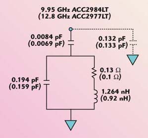
Fig. 3 Resonator equivalent circuit models.
In VCOs intended to provide a fixed frequency reference, as in SONET and many communications receivers, maximum circuit loaded Qs are limited by several tolerance elements: frequency set-on accuracy, frequency stability over operating temperature range and aging effects. The frequency set-on accuracy is generally dominated by the resonator. With unshielded resonators (for example, dielectric resonators), a combination of mechanical and electrical tuning are typically employed due to tolerances of the resonator, assembly and housings. The ceramic resonator can be manufactured to a frequency tolerance of less than 0.1 percent at 9.95 GHz. Typical frequency stability of a 9.95 GHz resonator is 1 MHz over the –20° to +80°C temperature range (averaging less than 2 ppm/°C), as shown in Figure 4. The resonators are not microphonic and exhibit no aging. Because the device is shielded, the frequency stability is not dependant on the housing or nearby materials. The frequency stability and precision enable the use of higher loaded Qs and result in improved phase noise. Integration of the ceramic resonator into microwave circuits is particularly simple; a chip and wire version with thin film gold metallization is illustrated in an oscillator assembly in Figure 5. The resonator shield can be used as the circuit RF ground plane enabling precise control over the chip to resonator connection. Table 2 summarizes the characteristics of the resonators. An SMT assembly incorporating a bumped solderable resonator is illustrated in Figure 6. Parts are provided in waffle pack or tape and reel.

Fig. 4 The 9.95 GHz resonator frequency stability vs. temperature..


Fig. 5 A ceramic resonator wirebond assembly.