With recent advances in telecommunications, the use of microstrip antennas is increasing for a wide range of modern microwave systems. This is mainly due to the features of microstrip antennas: low profile, lightweight, conformable to nonplanar surfaces, and easy and inexpensive mass production. They are well suited for integration with their feeding networks and microwave devices, using modern microwave integrated circuit technology. Microstrip antenna arrays have a wide range of applications in civil, military or scientific domains. Today, an increasing number of radio services, such as communications, navigation and broadcasting, must be available and a single antenna must be operating for several applications. Therefore, much research has been conducted both on antenna miniaturization and multi-band operation.

The ring printed antennas are well known for their multi-band abilities and advantageous characteristics. They are used in communication systems, and several structures have been recently proposed in the literature.1–4 Usually, the designer needs to alternate between circuit and electromagnetic simulation tools to design the feed circuit and the radiating elements. The design and development of a linear array in microstrip technology may be made easier by combining commercially available CAD software tools, such as the Agilent ADS and Agilent Momentum planar electromagnetic solver.5 They are suitable for modeling microstrip patch antenna elements, feeding transmission lines in radiating layers, optimization and layout production. The proposed design is described in detail in this article and experimental results for the prototype built are presented and discussed.

Antenna Design
Two procedures are used to design the compact dual-band antenna. The first step is the design of the radiating element and the second concerns the power divider.
Radiating Element
The radiating element is a ring patch fed by a power divider and is printed on the same substrate. The dimensions of the antenna have been simulated to operate at the desired frequencies. Quarter-wave transformers have been used in order to match the antenna input ports to the power divider output ports. The antenna mask layout with its quarter-wave transformer is shown in Figure 1.
Power Divider
A corporate power divider with four output ports, able to operate from 10 to 14 GHz, has been designed for equal phase and power level at all outputs with a high isolation between ports. In order to reduce the mutual coupling effects between adjacent patches, the inter-element distance was chosen to be approximately 2?1, where ?1 is the wavelength corresponding to the lowest frequency. A symmetrical structure, well suited to obtain equal phase outputs, has been chosen. The power divider and antennas have been designed for the same epoxy substrate with a relative permittivity ?? = 4.55, loss tangent tan ? = 0.01 and thickness h = 1.55 mm. A 50 ? coaxial connector is used to feed the network. Figure 2 shows the proposed layout of the power divider.

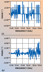
The simulated results, for frequencies between 11 to 13 GHz, are presented in Figure 3 for amplitude difference and Figure 4 for phase difference between output ports. Notice that both power and phase at the outputs are equal since the difference in amplitudes and phases are very close to zero.
Simulation Results
Return Losses and Input Impedance
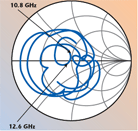
The simulated input reflection coefficient of the corporate fed antenna array is displayed in Figure 5. The dualband operation is emphasized by the two minimum return loss frequencies (10.8 and 12.6 GHz) with –32.7 and –34.5 dB, respectively. The bandwidth is 8.3 percent for the first frequency and 11.1 percent for the second one. Figure 6 shows that the input phase at the two operating frequencies are equal. The impedance locus at the input of the antenna array from 8 to 14 GHz is illustrated on the Smith chart in Figure 7. A very good match is obtained at the frequencies for which the impedance points are close to the Smith chart center, which corresponds to an ideal match.
Radiation Patterns

Figure 8 shows the radiation patterns at 10.8 GHz for E? (cross-polarization) and E? (co-polarization). Notice that the E? amplitude is higher than the E? amplitude, the first side lobes are less than –10 dB and the pattern exhibits an excellent symmetry. The E? amplitude does not show a main lobe and the side lobes are less than –7 dB. Figure 9 shows the antenna array gain, exhibiting a high directivity. The maximum gain of the antenna array is 9.5 for the first working frequency.
Experimental Results and Discussion
Figure 10 shows a photograph of the array, with its feeding network, which has been built and tested. The input reflection coefficient S11 has been measured using a HP5510 network analyzer and is shown in Figure 11. This experimental antenna array can operate at three distinct frequencies: 10.9, 13.0 and 15.1 GHz. The simulated and experimental results of the input return loss at the two resonant frequencies are shown in Table 1.

The bandwidths (?f/f0 at –6 dB), corresponding to the first and second frequency, are 7.3 and 8.4 percent, respectively. The simulated frequencies, f1 = 10.8 GHz and f2 = 12.6 GHz, are close to those measured. The shift observed for the second frequency can be due to various reasons, such as tolerances in the electrical and mechanical parameters of the dielectric material, and/or manufacturing problems.
Conclusion
A four-element linear array of ring patches, with a planar microstrip feed network operating in the X- and Ku-bands for satellite communications with a linear polarization, was successfully simulated and designed. The dual-band is obtained by using a ring antenna as a radiating element. The simulation was conducted using Agilent ADS and Momentum software. A prototype was built and tested, which satisfies in general the requirements for the application.

References
1. B.L. Ooi, S. Qin and M.S. Leong, “Novel Design of Broadband Stacked Patch Antenna,” IEEE Transactions on Antennas and Propagation, Vol. 50, No. 10, October 2002.
2. E. Gschwendtner and W. Wiesbeck, “Ultra-broad Car Antennas for Communications and Navigation Application,” IEEE Transactions on Antennas and Propagation, Vol. 51, No. 8, August 2003.
3. K.L. Wong, G.Y. Lee and T.W. Chiou, “A Low Profile Planar Antenna for Multi-band Operation of Mobile Handsets,” IEEE Transactions on Antennas and Propagation, Vol. 51, No. 1, January 2003.

4. J.M. Laheurte, “Dual-frequency Polarized Antennas Based on Stacked Monofilar Square Spirals,” IEEE Transactions on Antennas and Propagation, Vol. 51, No. 3, March 2003.
5. Momentum, Agilent Technologies Inc., Santa Rosa, CA, 2000.
6. J.M. Ribero, R. Staraj and J.P. Damiano, Antennas and Associated Systems for Mobile Satellite Communications, M.E. Bialkowsky, Ed., “Analytical Models for Fast Analysis and Synthesis of Various Printed Antennas,” University of Queensland, Australia, pp. 23–39.
Mehadji Abri received his state engineer and master diplomas from Abou Bekr Belkaïd University in 2001 and 2004, respectively. He is currently a junior researcher within the telecommunications laboratory. His main research interests include the analysis and synthesis of multi-band antennas and arrays.
Noureddine Boukli-Hacene received his diplome d’etudes approfondies in microwave engineering (DEA communications optiques et microondes) and his doctorate degree (prepared at the Centre National d’Etudes Spatiales, Toulouse, France) in electrical engineering from Limoges University, France, in 1982 and 1985, respectively. He is now a lecturer at the University Abou Bekr Belkaïd, Tlemcen, Algeria. His research interests include microstrip antennas and microwave circuits.

Fethi Tarik Bendimerad received his state engineer diploma in 1983 from Oran Sciences and Technologies University, Algeria, and his doctorate degree from Nice Sophia Antipolis University, France, in 1989. He is currently a professor and director of the Telecommunications Laboratory at the University Abou Bekr Belkaïd, Tlemcen, Algeria, where he is responsible for the antenna section. His main research interest is microwave techniques and radiation.
Edmond Cambiaggio received his PhD degree in physics from the University of Marseille, France, and his French ‘doctorat d’ etat’ degree in physics from the University of Nice, France, in 1970 and 1978, respectively. He is currently the head of the department of electronics at the University of Nice – Sophia Antipolis. His research interests include microstrip antennas, microstrip antenna arrays, conformal antennas, conformal arrays, and the simulation and modeling of antennas.


Mehadji Abri

Noureddine Boukli- Hacene

Fethi Tarik Bendimerad

Edmond Cambiaggio

