
The diplexer, commonly used to make receiving and transmitting share a common antenna, is an essential three-port device and typically consists of several bandpass (BPF) and bandstop (BSF) filters. Consequently, the performance of the BPF determines the comprehensive performance of the diplexer to a great extent. However, with recent advances and development in microwave and millimeter-wave receiver technology, a great demand for compact, low cost and high performance diplexers has been created. Several authors have focused on these issues and extensive research has been performed1-8 using microstrip technology.
Although open-circuited stubs1,2 can be adjusted for bandwidth and out-of-band rejection requirement, they increase the insertion loss and circuit size. Stepped impedance coupled-line resonators have been used to realize a high isolation hairpin line diplexer,3 but it also brings other issues of large size and design complexity. The miniaturization issue was considered,4 but the suppression of spurious response is still dependent on a tapped open-circuited stub. The frequency selectivity and isolation is fulfilled by cascading multi-complementary split ring resonators (CSRR),5 but the occupied area is still a little large. Lumped-element loaded composite right-/left-handed transmission lines (CRLH TL)6,7 is a good strategy for size reduction, but the operating frequency is limited due to self resonance. The integration of a diplexer and balun by adopting half-wavelength open-loop resonators8 is implemented for low cost but the circuit area is a problem. In this article, the compact and high performance issues are addressed by introducing the fractal geometry into the design of new concept CRLH TL. The wideband harmonic suppression and frequency selectivity are realized by only one CRLH cell, which distinguish the current design from previous ones.

Figure 1 Topology of the proposed diplexer.
Diplexer Design
Figure 1 shows the topology of the fabricated microstrip diplexer, with an occupied area is only 15.6 × 28 mm (namely 0.15λg × 0.275λg, λg being the signal wavelength at 1.8 GHz). Note that the K-ECSSRRP, the ground plane and the conductor line are depicted in white, light grey and dark grey, respectively. The width of the K-ECSSRRP Tx filter is 0.3 mm and 0.2 mm for the Rx filter. The inner ring of the Tx filter is constructed by three Koch curves of the second order and a Koch curve of the first order. The ring for the Rx filter is almost the same, but a stub is added at the end of the first order curve. As can be seen, the diplexer consists of three ports, a receiver (Rx) and a transmitter (Tx) filter cascaded at the output lines. The Rx and Tx filters, engineered to provide passbands centered at 1.8 and 2.2 GHz, respectively, are implemented by only one CRLH TL cell, which is the key factor of super compact performance. The CRLH TL cell is composed of a Koch-shaped extended complementary single split ring resonator pair (K-ECSSRRP), etched in the ground plane and a series capacitive gap etched in the conductor strip. The K-ECSSRRP can be constructed by inserting four identical Koch-curve-shaped rings in the complementary single split ring resonator pair (CSSRRP). The resultant four rings extend the current paths, thus allowing a more compact unit cell, and introduce additional attenuation poles at the frequency of spurious responses, which enables better frequency selectivity and wideband harmonic suppression.

Figure 2 Circuit model of the K-ECSSRRP-loaded CRLH TL.
The circuit model (losses have been excluded) of K-ECSSRRP-loaded CRLH TL is shown in Figure 2. An additional shunt branch is added to model the influence of four inserted Koch-shaped rings on the overall performance of the filter. Consequently, the current structure enhances the design flexibility to a great extent. In this model, Ls represents the line inductance, Cg models the series gap capacitance, CSSRRP is described by means of a parallel resonant tank formed by Lp1, Cp1, and Ck1, C1 represents in part the line capacitance and in part the electrical coupling through the series gap to the CSSRRP. In like manner, the other shunt branch formed by C2, Lp2, Cp2, and Ck2, models the corresponding effect of the Koch-shaped small ring.
Two transmission zeros are obtained and calculated as follows, when the two shunt branches resonate according to the circuit model.

The lower limit of the RH band fLRH can be inferred when the series branch resonates.

The admittance of the shunt branch consisting of two shunt admittances is formulated as

Therefore, the upper limit of LH band fHLH is achieved by forcing Y to be null. When fLRH = fHLH, the balanced condition is fulfilled and there is continuous transition between a left- handed (LH) band and right-handed (RH) band. Moreover, the Bloch impedance, which is associated with series impedance Zs and shunt impedance Zp as follows, is forced to be null to obtain the lower limit of LH band fLHL and the upper limit RH band fHRH

The deductions of fHLH, fLRH and fHRH involve tedious calculation, thus are not reproduced here, but can be easily illustrated by their representations with a computer.

Figure 3 Comparison of S-parameters obtained by EM simulation and electrical simulation.
Equations 1 to 5 have been engineered as design guidelines to control the center frequency, bandwidth and selectivity (transmission zeros) of the Tx and Rx filters. As a demonstration, the frequency response (see Figure 3) of a K-ECSSRRP-loaded CRLH TL whose geometrical parameters are kept the same as Tx filter but with a narrower conductor line and series gaps whose widths are 2 and 0.2 mm, respectively, is obtained from a full-wave electromagnetic (EM) simulation using Ansoft Designer and an electrical simulation (circuit model) through Ansoft Serenade. The frequency response of CSSRRP-loaded CRLH TL with identical geometrical parameters is also provided for comparison. The analysis and current diplexer design are implemented on RT/duroid 4300C substrate with a dielectric constant of 3.38 and a thickness of 0.5 mm. The extracted lumped elements are: Ls = 31.2 nH, Cg = 0.26 pF, C1 = 6.74 pF, Ck1 = 351.4 pF, Cp1 = 0.59 pF, Lp1 = 4.26 nH, C2 = 1.33 pF, Ck2 = 2.16 pF, Cp2 = 0.1 pF, Lp2 = 4.84 nH.
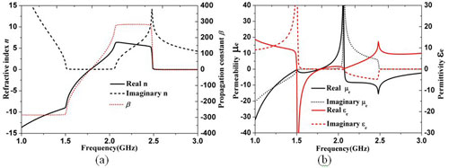
Figure 4 Retrieved constitutive EM parameters of K-ECSSRRP-loaded CRLH TL based on S-parameters.
Consistent results between EM and electrical simulations can be observed. The slight discrepancy is due to the wideband considered, because any circuit model would deteriorate when the scope exceeds an appropriate frequency range. It is worth mention that the third attenuation pole in the EM simulation is due to the inherent periodicity of the physical structure and is, hence, impossible and does not need to be considered in the circuit model. A further inspection reveals that the Koch-shaped ring in CSSRRP, not only produces an additional transmission zero and shifts the inherent attenuation pole toward the lower band above the edge of the passband, but also results in a significant lower operating frequency, which is reduced from 2.7 to 1.8 GHz (a frequency downscale of 33 percent). The retrieved constitutive EM parameters shown in Figure 4, based on an improved NRW method,9 give strong support to the balanced composite LH and RH passband behavior. Very obvious negative refractive index and backward wave propagation are obtained in the frequency range of 1.53 to 1.79 GHz (namely LH band). The RH band occurs around 1.79 to 2.05 GHz when these values are positive. Moreover, the K-ECSSRRP is still responsible for the negative permittivity. The negative permeability in the vicinity of the magnetic resonance is the key factor of the transmission zero located above the passband.
Given the determined Tx and Rx filters, the optimization of the final geometry of the diplexer is indeed very crucial. The conductor line is set to be 1.2 mm, corresponding to characteristic impedance of a standard 50 Ω SMA connector, while the width of the upper conductor lines of the Tx and Rx filters is adjusted for the comprehensive impedance match performance, which accordingly distinguishes them from ones in separate Tx or Rx filters.

Figure 5 Photograph of the fabricated diplexer in an enclosure.
Numerical and Measurement Results
The performance of the proposed diplexer has been assessed with Ansoft Designer. For verification, the diplexer was fabricated and measured with Anritsu ME7808A vector network analyzer. Figure 5 shows a photograph of the fabricated prototype in an enclosure for practical military multi-service and multi-band communication systems application, while Figure 6 compares the simulated and measured S-parameters. Reasonable agreement can be observed. The measured bandwidth of the Tx filter is 220 MHz for the 1.61 to 1.83 GHz range, in which the return loss |S11| is better than 10 dB and the insertion losses |S21| and |S31| are better than 1.5 dB. The measured bandwidth of Rx filter is 330 MHz for the 2.08 to 2.41 GHz range, in which |S11| is better than 10 dB, |S21| and |S31| are less than 1.3 dB. Moreover, at the two target frequencies, |S11| = 13.3 dB, |S21| = 0.95 dB, |S31| = 14.8 dB and |S11| = 28.5 dB, |S21| = 23.9 dB, |S31| = 0.58 dB. The wide out-of-band suppression, better than 20 dB up to 3.66 GHz, should be highlighted.

Figure 6 Measured and simulated S-parameters of the diplexer.
Conclusion
For the first time, a compact diplexer has been presented by means of an initially proposed K-ECSSRRP. The proposed K-ECSSRRP with a dimension of 0.107λg is electrically very compact. The induced addition of transmission zero and frequency-shift transmission zero can be engineered at the frequency of spurious responses and thus enhance the harmonic suppression and selectivity to great extent. The resultant diplexer, which exhibits a low profile and a highly integrated circuit in conjunction with the enhanced selectivity and harmonic suppression, can find wide applications in transceiver front-ends of mobile and wireless local area network (WLAN) systems, phased-array transceiver systems and even military multi-service and multi-band communication systems where miniaturization is a concern.
Acknowledgments
This work is supported by the National Natural Science Foundation of China under Grant No. 60971118. Special thanks should also be delivered to 206th Institute of China for the fabrication and encapsulation.
References
- B. Strassner and K. Chang, "Wide-band, Low-loss High-isolation Microstrip Periodic-stub Diplexer for Multiple-frequency Applications," IEEE Transactions on Microwave Theory and Techniques, Vol. 49, No. 10, October 2001, pp. 1818-1820.
- S. Hong and K. Chang, "Stub-tuned Microstrip Bandpass Filters for Millimeter-wave Diplexer Design," IEEE Microwave and Wireless Components Letters, Vol. 15, No. 9, September 2005, pp. 582-584.
- S. Srisathit, S. Patisang, R. Phromloungsri, S. Bunnjaweht, S. Kosulvit and M. Chongcheawchamnan, "High Isolation and Compact Size Microstrip Hairpin Diplexer," IEEE Microwave and Wireless Components Letters, Vol. 15, No. 2, February 2005, pp. 101-103.
- M.H. Weng, C.Y. Hung and Y.K. Su, "A Hairpin Line Diplexer for Direct Sequence Ultra-wideband Wireless Communications," IEEE Microwave and Wireless Components Letters, Vol. 17, No. 7, July 2007, pp. 519-521.
- J. Bonache, I. Gil, J. García-García and F. Martin, "Complementary Split Ring Resonators for Microstrip Diplexer Design," Electronics Letters, Vol. 41, No. 14, July 2005, pp. 810-811.
- J. An, G.M. Wang, C.X. Zhang and P. Zhang, "Diplexer Using Composite Right-/left-handed Transmission Line," Electronics Letters, Vol. 44, No. 11, May 2008, pp. 685-687.
- H.X. Xu, G.M. Wang and H.P. An, "Hilbert Fractal Curves Form Compact Diplexer," Microwaves & RF, Vol. 49, No. 8, August 2010, pp. 92-96.
- Z.H. Bao, J.X. Chen, E.H. Lim and Q. Xue, "Compact Microstrip Diplexer with Differential Outputs," Electronics Letters, Vol. 46, No. 11, May 2010, pp. 766-768.
- H.X. Xu, G.M. Wang and J.G. Liang, "Novel CRLH TL Metamaterial and Compact Microstrip Branch-line Coupler Application," Progress in Electromagnetics Research C, Vol. 20, 2011, pp. 173-186.