
As people are taking advantage of the convenience of mobile and wireless communications, the demands are increasing on technological evolution in the field of telecommunications. From communication methodologies to portable device fabrication, developers are facing challenges and striving to tackle the problems. In the meantime, smartphones have provided numerous application programs and mobile Internet services, started through WiMAX and LTE technologies. The handset phones for the aforementioned function should be robust, in a complicated and tough environment, to guarantee the quality of communication and be small for commercial success. This is heavily determined by the hardware of the phones, including the antennas.
The multi-input multi-output (MIMO) antenna was proposed to handle the harsh wireless communication environment, by providing diversity in RF signal transmission and reception and has motivated the antenna community, where size reduction is a hot issue, along with high isolation between multi antennas. A. Mak et al.1 introduced a set of antennas with a structure that traps the near-field coming from one antenna to the other, based upon a local current loop disconnecting a fictitious enlarged loop of current in order to secure the isolation. The antennas have acceptable radiation pattern and isolation, but in terms of size, the radiators and the trap take the top edge and two sides of the handset ground. K. Payandehjoo et al.2 adopted an EBG geometry to increase the diversity gain by preventing coupling between two antennas. However, the size exceeds the industrial standard and the working frequency is away from the WiMAX band. X. Wang et al.3 described two microstrip-fed antennas. Their vertical and layered radiating parts stand perpendicular to the handset stratified ground by folding and periodically meandering a decoupling structure for improving the isolation. Although it has an isolation greater than 12 dB, this structure is a microstrip-fed, monopole-type, decoupling geometry, with three dimensionally folded radiators, the volume of which takes most of the ground.

It is pointed out that these antennas and the decoupling structure should be size-reduced while having antenna performances meeting the industrial requirements. Recently, metamaterials (MTM) technologies were introduced and have suggested alternative ways to overcome the limitations in improving electrical performances and reducing the sizes of components and resonators.4,5 Lumped elements of series capacitance and shunt inductance are loaded in a transmission line to generate nonlinear dispersion characteristics due to the composite right- and left-handedness (CRLH), including the ZOR due to the in-phase field over a corresponding MTM resonator. While the CRLH and ZOR are mentioned with the electromagnetic bandgap (EBG) of an array of the mushroom (a patch connected to the ground through a pin),4 the SRRs are adopted to fit a resonator into a confined area, on account of the end-gap and inter-ring capacitances.6 The SRRs create a resonance, so they can be applied to not only to filters, but also to antennas.7 The SRR is designed to make one antenna, but its size is approximately 30 × 40 mm and not appropriate for the mobile MIMO antenna, considering that two antennas of its kind and the decoupling structure between them, will result in an overall horizontal length over 90 mm. This shortcoming results from the fact that their SRRs do not have the ZOR or metamaterial properties.
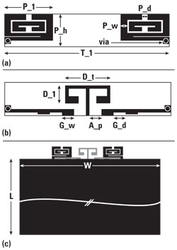
Figure 1 Structure of the proposed MIMO antenna (a) top surface, (b) bottom surface and (c) antenna at top edge of handset ground.
In this article, a miniaturized MIMO antenna that has novel antenna elements and a decoupling geometry is described. It aims to satisfy size, antenna performance and isolation required by WiMAX and LTE high band communications. The antenna elements look similar to SRRs, but they are much smaller than ordinary SRR antennas, since the proposed structure has a CRLH configuration and a ZOR field distribution. To suppress the coupling between the novel antennas, a planar mushroom is placed between them. Because this mushroom is planar, it is conveniently and inexpensively formed in the bottom grounding surface of the substrate of the MIMO antenna geometry. The design goes through full-wave simulations for monitoring and tuning S11, radiation pattern, ZOR field and isolation of the proposed antenna. It is then fabricated on an FR4 substrate and experimentally tested on the board of a real mobile phone. As a result, it is revealed that the return loss, isolation and radiation efficiency are better than 10 dB, over 12 dB, and over 50 percent, respectively, in the WiMAX and LTE high bands, for both the antennas, whose overall size is 26 × 5.5 × 2 mm. This is less than half of the top-edge of the handset ground, even when the proposed MIMO antenna is mounted in a mobile phone platform.

Figure 2 Return loss of the proposed antennas as a function of G_d.
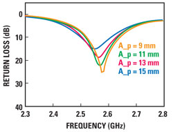
Figure 3 Return loss of the proposed antennas as a function of A_p.
Design of the Proposed MIMO Antenna
Prior to the design, the specifications shown in Table 1 are addressed. The element antennas have similarity to SRRs in that the inner open-gap ring is surrounded by the outer ring. Different from the ordinary SRRs, one corner of the outer ring is connected to a transmission line (upper transmission line or UTL), that is coupled through the electric field and current to another transmission line (lower transmission line or LTL), attached to the ground. The element antennas' SRRs and the UTL are placed on the top surface of the 2 mm-thick FR4 substrate, whose bottom surface has the feeding points with the handset ground, the planar mushroom and the LTL as shown in Figure 1. The handset ground has an area (W × L) of 50 × 80 mm. The aim of the proposed design is to reduce the size of the resultant antenna to less than 70 percent of W. Since the conventional SRR has a right-handed resonance, at first sight, it seems improper for effective size-reduction. So each of the antennas, 1 and 2, has the SRR play the role of the series capacitance (CL) and part of the series inductance (LR) in implementing the CRLH characteristics. Simultaneously, the electric field coupling and current flowing between the upper and bottom transmission lines are equivalent to part of the shunt capacitance (CR) and the shunt inductance (LL), respectively. Besides, the bottom transmission line provides inductance and capacitance factors of the right-handed transmission line as LR and CR. In principle, the approach of the CRLH equivalent circuit is very similar to that of Jang et al.5 The factors are adjusted to have the CRLH ZOR, which enables the proposed SRR to be much smaller than the conventional SRRs. The ZOR field will be given later in the article. Pursuing the realization of the metamaterial ZOR properties for this structure, the following parametric studies are conducted. Along with G_w, G_d accounts for the impedance matching and manipulating the main part of CR. In Figure 2, the return loss (S11) is plotted for different values of G_d, with P_l, P_h, P_d, P_w and G_w set to 10, 5, 1, 0.8 and 2.0 mm, respectively. G_d ranges from 0.5 to 2.0 mm and four samples are taken. With a 10 dB criterion, G_d values of 1.5 mm and above are acceptable. This implies that the proposed miniaturization method requires a certain collective shunt capacitance of CR, maintaining G_d. Figure 3 shows the return loss of the antenna as a function of the feeding positions (A_p), with respect to the decoupling structure, with the other parameters P_l, P_h, P_d, P_w, G_w and G_d fixed as 10, 5, 1, 0.8, 2.0 and 2.0 mm, respectively. A_p is varied from 9 to 15 mm. It shows that once A_p is set over 9 mm with the other parameters chosen as above, the change of the return loss seems insensitive to the distance between the planar mushroom and either of the element antennas. In a similar manner, all the physical dimensions are found to achieve the antenna functions required by the WiMAX and LTE high bands, through impedance matching and electromagnetic interactions between the radiators, transmission lines, feeding points, handset ground, etc. Before moving to the proposed planar mushroom to decouple the interference between antennas 1 and 2, the ZOR characteristic is proven by the electric field distribution over either of the element antennas. This full-wave simulation is performed with the CST-MWS.8 While the conventional SRRs have an out-of-phase electric field distribution, in a physical structure that is manipulated for the same resonance frequency and larger than the proposed antenna, the ZOR antenna with a size 0.2 times that of the top-edge is resonant at the center frequency. The ZOR results in the in-phase electric field vectors (all directed upward) and contribute the lower interference to the neighboring antenna (see Figure 4).

Figure 4 In-phase electric field distribution of the ZOR at the center frequency.

Figure 5 Isolation (S12) before and after placing the planar mushroom.
Next, a planar mushroom is proposed to enhance the isolation. As far as the MIMO antenna is dealt with, the isolation between the multiple antennas is one of the most crucial factors in the design. The less the antennas are correlated or coupled, the higher the antenna isolation is, which means the signal survives multiple reflection and fading in a wireless environment with higher probability. As shown in Figure 5, with the help of the planar mushroom as the decoupling structure, the isolation is increased from 8 to 19 dB, which is far better than the specification. When the MIMO antenna is designed for increasing the best isolation, the return loss (S11) is optimized as 27 dB. These values, S11 and S12, are preparation for the possible degradation that can be caused by the physical placement on the real phone platform. Besides, the frequency response of the two antennas with the decoupling structure of D_t of 6.5 mm and D_l of 3.0 mm, the surface current densities are plotted in Figure 6 to determine how the increased isolation is obtained. Obviously, the planar mushroom, centered in the entire MIMO antenna system, decouples the connection between antennas 1 and 2. In other words, the decoupling structure draws the surface current due to the near- field from one excited antenna and plays the role of a trap. Consequently, the isolation between the element antennas is enhanced.
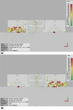
Figure 6 Surface currents on isolated antennas (a) from antenna 1 to antenna 2 and (b) from antenna 2 to antenna 1.

Figure 7 Proposed antenna tested on a real board.
Fabrication and Measurement
After the design phase, based upon the theoretical and numerical approaches, the proposed antenna was manufactured for experimental verification. As simulated in a full-wave analysis frame, a simple microstrip MIMO antenna is made on an FR4 substrate with εr = 4.3 and a thickness of 2 mm. The overall size of the proposed antenna is 26 × 5.5 × 2 mm, which amounts to just within half of the top-edge of the ground of handset phones. Figure 7 shows the antenna mounted on the phone platform with a cover. After extra trimming work, the proposed antenna was simulated to give the return loss and isolation as shown in Figure 8. The best performance (|S11| and |S22| < −25 dB, |S21| < −19 dB) is achieved, in case of degradation in manufacturing and real environment test. The measured return loss and isolation (|S11| and |S22| < −22.5 dB, |S21| < −12 dB) complies with the specifications. Figure 9 presents the radiation patterns in the E- and H-planes, where the two antennas have similar omni-directional far-field plots, desirable in MIMO communications, even with the isolation of over 12 dB. Lastly, the radiation efficiency and peak and average gains are measured as shown in Figure 10. The plot shows that the efficiency is over 50 percent. Simultaneously, the peak gain is 2.25 dBi at the center frequency, which is acceptable to the industry, with an average gain of −2.7 dB. In summary, all the electrical performances and the physical size of the proposed MIMO antenna are compliant to the design specifications.

Figure 8 Antenna performance while mounted on a real board (a) simulation and (b) measurements.
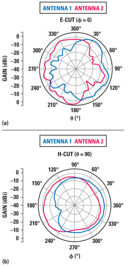
Figure 9 Radiation patterns of the antenna (a) E-plane and (b) H-plane.

Figure 10 Gain and efficiency of the antenna.
Conclusion
This article has presented a novel compact MIMO antenna, which has enhanced isolation between very small antenna elements. The antennas are miniaturized for the first time with the proposed ZOR SRRs, which have the in-phase field behavior and a size of 0.2 times the top-edge of the handset ground. A planar mushroom, used as the decoupling structure between antennas 1 and 2, suppresses the mutual coupling and improves the isolation. Through full-wave simulations, the ZOR properties of the antennas and the decoupling between them have been proven. The antenna has been fabricated and tested in a real phone platform, showing a return loss better than 10 dB, an isolation greater than 12 dB and a radiation efficiency over 50 percent in WiMAX and LTE high bands, for both antennas, which have a total size of 26 × 5.5 × 2 mm. Considering these performances, this proposed antenna can be employed for developing small MIMO communication systems.
Acknowledgment
Sungtek Kahng, as the principal author with the University of Incheon, would like to thank LG Innotek for providing great opportunities to work on the MIMO antenna development. This work is part of a patent being filed.
References
1. A.K. Mak, C.R. Rowell and R.D. Murch, "Isolation Enhancement Between Two Closely Packed Antennas," IEEE Transactions on Antennas and Propagation, Vol. 56, No. 11, November 2008, pp. 3411-3419.
2. K. Payandehjoo and R. Abhari, "Employing EBG Structures in Multiantenna Systems for Improving Isolation and Diversity Gain," IEEE Antennas and Wireless Propagation Letters, Vol. 8, 2009, pp. 1162-1165.
3. X. Wang, Z. Feng and K.M. Luk, "Pattern and Polarization Diversity Antenna With High Isolation for Portable Wireless Devices," IEEE Antennas and Wireless Propagation Letters, Vol. 8, April 2009, pp. 209-211.
4. C. Caloz, C. and T. Itoh, "Electromagnetic Metamaterials: Transmission Line Theory and Microwave Application," John Wiley & Sons, Somerset, NJ, 2006.
5. G. Jang, S. Kahng, J. Ju, J. Anguera and J. Choi, "A Novel Metamaterial CRLH ZOR Microstrip Patch Antenna Capacitively Coupled to a Rectangular Ring," 2010 IEEE APS URSI Conference Digest, pp. 1-4.
6. R. Marques et al. "Metamaterials with Negative Parameters: Theory, Design and Microwaves Applications," John Wiley & Sons, Somerset, NJ, 2008.
7. X. Yang, Z. Yu, Q. Shi and R. Tao, "Design of Novel Ultra-wideband Antenna with Individual SRR," Electronics Letters, Vol. 44, 2008, pp. 1109-1110.
8. www.cst.com, April 2011
Seongryong Yoo received his bachelor's degree in engineering from the University of Incheon (UI), Incheon, Korea, in 2010. He is working on his master's degree on radio science and engineering at the Department of Information and Telecommunication Engineering in the University of Incheon. His research fields are antennas, microwave components and metamaterials.
Sungtek Kahng received his doctorate in electronics and communication engineering from Hanyang University, Korea, in 2000, with specialty in radio science and engineering. From 2000 to early 2004, he was with the Electronics and Telecommunication Research Institute, where he worked on numerical electromagnetic characterization and developed RF passive components for satellites. In March 2004, he joined the Department of Information and Telecommunication Engineering at the University of Incheon, where he has continued research on analysis and advanced design methods of microwave components and antennas, including metamaterial technologies, MIMO communications and wireless power transfer.
Jong-Guk Kim received his master's degree in mechatronics engineering from Gwang-ju Institute of Science & Technology (GIST) Graduate School, Gwang-ju, Korea, in 2004, with the design and analysis of X-Band mixer-type phase detectors. He is working on his doctorate in management of technology in the University of Sungkyunkwan, Suwon, Korea. In June 2004, he joined the department of Network Solution Group at the LG Innotek Co. Ltd.