
Achieving the ITU's IMT-Advanced 4G target peak data rates of 1 Gbps in the downlink and 500 Mbps in the uplink requires bandwidths that are wider than the maximum 20 MHz bandwidth specified in 3GPP Release 8/9 LTE. To achieve those targets, 3GPP Release 10 LTE-Advanced supports carrier aggregation, allowing two or more component carriers (CC) to be aggregated to create wider transmission bandwidths of up to 100 MHz. Most operators are unlikely to find 100 MHz of contiguous bandwidth in the available spectrum resources, so the ITU has allowed the use of both contiguous and non-contiguous carrier aggregation. In the latter case, the component carriers can be non-contiguous in the same spectrum band (intra-band) or non-contiguous in different spectrum bands (inter-band). This article presents an overview of carrier aggregation along with some of the associated design and test challenges from the physical layer perspective for both the base station and the user equipment (UE). The type of test equipment that will be required to tackle these challenges is also considered.
To meet different spectrum and deployment plans, 3GPP Release 8/9 LTE introduced six carrier bandwidths of 1.4, 3, 5, 10, 15 and 20 MHz. However, to achieve the ITU's IMT-Advanced 4G target downlink peak data rate of 1 Gbps, even wider bandwidths are required. IMT-Advanced sets the upper limit at 100 MHz, with 40 MHz the expectation for minimum performance. Because most spectrums today are occupied and 100 MHz of contiguous spectrum is not available to most operators, the ITU has allowed the creation of wider bandwidths through the aggregation of multiple component carriers. Carrier aggregation has been adopted in 3GPP Release 10, better known as LTE-Advanced.
Three aggregation scenarios are defined in Release 10: single-band (or intra-band) contiguous carrier aggregation, single-band non-contiguous carrier aggregation and multi-band (inter-band) non-contiguous carrier aggregation. Component carriers of the same or different bandwidths (1.4 to 20 MHz) may be aggregated.
Release 10 component carriers are essentially the same as the carrier bandwidths defined in Release 8/9. In this way, LTE-Advanced maintains backward-compatibility with LTE. A Release 10 UE, with carrier-aggregation reception or transmission capability, can simultaneously receive or transmit on multiple component carriers corresponding to multiple serving cells. However, a Release 8/9 UE can receive or transmit on a single component carrier corresponding to one serving cell only.

Figure 1 Contiguous allocation of component carriers.
Figure 1 shows an example of inter-band carrier aggregation, in which five adjacent component carriers, each 20 MHz wide, covering the maximum 100 MHz LTE-Advanced bandwidth. For most operators today, this scenario is not realistic, since most operators do not have more than 20 MHz in a given frequency band. However, such contiguous allocation of component carriers may be realistic when new spectrum bands, such as 3.5 GHz, become available to operators in some countries.
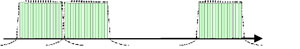
Figure 2 Intra- or single-band non-contiguous allocation of component carriers.
Figure 2 shows an example of intra-band non-contiguous aggregation, in which the component carriers are separated within a single frequency band. This scenario can be applied if multiple operators share a network or if the frequency band allocated to an operator is fragmented.

Figure 3 Inter- or multi-band non-contiguous allocation of component carriers.
Figure 3 shows an example of inter-band non-contiguous aggregation, in which component carriers belonging to different frequency bands (such as 1.8 and 2.6 GHz bands in some parts of Europe) are aggregated. Carriers aggregated in each frequency band can be contiguous or non-contiguous. The inter-band scenario for the downlink (base station to UE) is more realistic today because spectrum allocation for operators is often scattered across multiple frequency bands. However, for the uplink (UE to base station), this scenario would be very challenging because it would require multiple transceivers in the UE.

Figure 4 Data aggregation from the PHY up to the MAC interface.
Mapping of the component carriers, from the physical layer (PHY) up to the medium access control (MAC) layer interface, is shown in Figure 4. There is one transport block (in the absence of spatial multiplexing) and one Hybrid Automatic Repeat Query (HARQ) entity for each scheduled component carrier (HARQ is the control mechanism for retransmission). Each transport block is mapped to a single component carrier only. A UE may be scheduled over multiple component carriers simultaneously. The details of how the control signaling will be handled across the multiple component carriers are still being developed by 3GPP.

Operating Bands for Carrier Aggregation
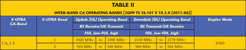
The operating bands currently specified in Release 10 for LTE-Advanced carrier aggregation are defined in Tables 1 and 2. These bands are defined for intra-band contiguous and inter-band non-contiguous cases. As more deployment scenarios are agreed upon based on operator input, more band definitions will be added to the specification independent of the Release version.
Design Challenges
Carrier aggregation brings new technical challenges, especially for the LTE-Advanced UE. The complexity of the UE's radio frequency (RF) front-end implementation can vary greatly, depending on which type(s) of carrier aggregation are supported, with contiguous carrier aggregation being the least complex. In Release 10 devices, contiguous carrier aggregation will not exceed two component carriers or 40 MHz maximum. It may be possible to support this configuration with a single wideband transceiver in the UE.
For non-contiguous component carrier allocations, the UE will have to use multiple transceivers or a single, very wide wideband transceiver. Using multiple transceivers may be realistic in the sense that such configuration requires only the addition of parallel paths to process each spectrum band, as in current multi-band devices. However, using multiple transceivers also increases the size and cost of the mobile device and shortens the battery life.
In the case of the wideband transceiver, a single transceiver must process the multi-band non-contiguous aggregation using wideband RF components. There are two main issues with this approach. First, as the bandwidth increases, the effective noise increases as well. Second, with a wider bandwidth, more undesired signals are likely to be received from other services. Thus for non-contiguous aggregation, most proposals today are trending toward the use of multiple transceivers instead of a single wideband approach.
In addition to increasing the RF front-end complexity, using simultaneous non-contiguous transmitters creates a highly challenging radio environment in terms of spur management and self-blocking. Because these challenges particularly impact UE design, more work needs to be done before inter-band carrier aggregation can be successfully introduced in the uplink. This is expected in 3GPP Release 11. However, for the LTE-Advanced base station, intra- and inter-band cases are defined in Release 10.

Figure 5 Release 10 transmission architecture options [3GPP TR36.807 VO.1.0 (2010-08)].
Defining the Test Requirements
Some of the test complexity in designing and testing LTE-Advanced equipment arises from the existence of simultaneous transceiver chains that require simultaneous tests of multiple transmitters. Figure 5 shows three different transmission architectures defined in Release 10. Type A supports two scenarios: intra-band contiguous carrier aggregation with a maximum of two Release 8 component carriers and a maximum uplink bandwidth of 40 MHz; and inter-band non-contiguous carrier aggregation with a maximum of two Release 8 component carriers. In this case, simultaneous transmission on both bands is not supported. Intra-band non-contiguous is not supported.
Type D1 currently supports two scenarios. One is intra-band contiguous carrier aggregation with a maximum of two Release 8/9 component carriers and a maximum uplink bandwidth of 40 MHz. The other is inter-band non-contiguous carrier aggregation with a maximum of two Release 8 component carriers, a maximum uplink bandwidth of 20 MHz, and support of simultaneous transmission on both bands. Type D1 has the capability to support intra-band non-contiguous carrier aggregation in future releases of the specification.
Type D2 currently supports two scenarios. One is intra-band contiguous carrier aggregation with a maximum of two Release 8/9 component carriers, a maximum uplink bandwidth of 40 MHz, and uplink MIMO support to address uplink peak data rate requirements. The other is inter-band non-contiguous carrier aggregation with a maximum of two Release 8 component carriers, a maximum uplink bandwidth of 20 MHz, and support of simultaneous transmission on both bands. Type D2 also has the capability to support intra-band non-contiguous carrier aggregation in future releases of the specification.
The different transmission configurations introduce a number of test challenges. For example, if a transmission configuration uses multiple transmitter antenna connectors, most of the evolved Node B (eNB) RF performance requirements will need to be applied at each antenna connector. Current LTE specifications for the eNB will be reused for LTE-Advanced as much as possible. For example, Release 8/9 requirements for transmitted signal quality tests (frequency error, EVM and downlink reference signal power) will be applied for each component carrier in a carrier aggregation scenario. The requirement for time alignment error between component carriers is being considered and the operating band unwanted emissions requirements for carrier aggregation transmissions have been aligned with those defined for the Release 8 multiple-carrier base station.
However, translating test requirements from Release 8/9 to Release 10 presents a number of difficulties. In the case of inter-band aggregation, synchronization must be maintained between the multiple transceivers, to allow simultaneous error vector magnitude (EVM) measurements on multiple component carriers. It has therefore been proposed for uplink to specify EVM only for those cases in which the power density is the same for both carrier allocations.
With intra-band non-contiguous carrier aggregation, there is a gap between the component carriers in which other technologies (for example, GSM or W-CDMA) could be transmitted. Physical layer transmit and receive measurements will need to be extended across the gap, to assess the interference caused by the co-existing, uncoordinated systems. This scenario increases the difficulty of defining limits to out-of-band emission tests, such as adjacent channel power and spectrum emission mask, and the details are still being worked out.
Multicarrier in-band emissions for the uplink pose another problem. The Release 8/9 requirement, based on a single wanted contiguous physical resource block (PRB), is too complex to scale up to a generalized multi-carrier requirement. Alternative ways of specifying carrier aggregation in-band emissions are being studied. The intention is to specify a general requirement that would apply, regardless of whether a single or dual transmitter architecture is used.
Characterizing the LTE-Advanced UE or eNB power amplifier presents still another RF challenge. The different carrier aggregation configurations will stress the amplifier in different ways, because each will have different peak-to-average ratios. In the case of the UE, a single transceiver may be used for contiguous carrier aggregation. Although the design is similar to that of a Release 8/9 UE, the power amplifier in the LTE-Advanced UE has to be capable of covering the wider bandwidth created by carrier aggregation.
Test Tools for LTE-Advanced Carrier Aggregation
Testing carrier aggregated signals requires instruments that can generate and analyze multiple-component carriers simultaneously. The key word here is "simultaneously." One of the biggest challenges facing engineers working on LTE-Advanced is how to analyze the multiple-component carriers at the same time, especially in the case of inter-band carrier aggregation, as no signal analyzer on the market has a bandwidth wide enough to cover multiple frequency bands. Existing LTE measurement instruments are capable of analyzing component carrier in one frequency band at a time, but to capture and analyze multiple component carriers, in different frequency bands simultaneously, requires advanced tools.

Figure 6 Agilent 89600 VSA Software for LTE-Advance controls two signal analyzers and measures up to five components simultaneously displaying results of each in a separate trace.
This problem has been solved by using two signal analyzers, each tuned to a relevant frequency band and synchronized. The analyzers are controlled with software developed specifically for LTE-Advanced testing that has the ability to acquire all the component carriers simultaneously from the two synchronized instruments, demodulate the captured signals and analyze them all simultaneously. An example of the results is shown in Figure 6. The software displays each component carrier measurement in a separate trace.

Figure 7 Agilent Signal Studio Software generates an aggregated signal consisting of five contiguous component carriers.
LTE-Advanced downlink and uplink signals compliant to the Release 10 standard are required to test power and modulation characteristics of components and transmitters. In Figure 7, signal generation software is used to create an aggregated signal with five component carriers. The software's built-in tools, such as CCDF, can be used to analyze compression and evaluate the required amplifier power back-off for different signal configurations.
Conclusion
Although the concept of carrier aggregation is simple, the changes it introduces at the physical layer are complex. With the introduction of carrier aggregation, asymmetric uplink and downlink allocations will become commonplace, driven by different numbers of component carriers in the uplink and downlink signals, the different bandwidths of component carriers that can be aggregated and the resulting combinations of component carrier number and bandwidth in an aggregated signal. The number of test cases for carrier aggregation would quickly become unmanageable if all contiguous and non-contiguous intra-band and inter-band combinations were considered. How to limit the allowed allocations in order to minimize the number of test scenarios is a major topic of discussion within the 3GPP.

Martha Zemede graduated from San Jose State University in 2000 with a bachelor's degree in electrical engineering and has taken postgraduate studies in wireless communications at Stanford University. She is working in the Microwave and Communications Division of Agilent Technologies, as an applications expert for 3GPP LTE/LTE-Advanced Signal Analysis solutions. In the past 11 years with Agilent, Zemede has worked in supporting the cellular communication technologies in Agilent's signal analyzers, as well as product marketing positions. She has also developed and led training courses and workshops on cellular wireless technologies for thousands of customers worldwide.