
Consumers are demanding more from their mobile devices – including increased bandwidth. They have become accustomed to the near universal data connectivity of smartphones, and are voracious for the applications that continually demand higher and higher data rates. Tablet computers also are becoming more popular, and their demands for constant connectivity and data usage are reportedly five times higher than those of smartphones.1 Laptops have not disappeared either. Consumers expect their laptops to have the same universal connectivity as their phones, running applications that demand higher data rates. Most laptops have wireless network connectivity built-in, and there is a growing market for USB dongles to provide connectivity with the latest high data rate standards. There is also an emerging market for new categories of connected devices, ranging from Internet Protocol TV (IPTV) to connected vehicles with wireless diagnostic, safety and infotainment capabilities.
What is driving these increased data rates? In the US, for example, the introduction of advanced smartphones is pushing some networks to their limits and frustrating consumers. We have all seen the growth of streaming audio and video, and this is just the tip of the iceberg. The exponential growth of social networking- related traffic is another key driver, as is online gaming. Perhaps the most compelling trend is the growth of cloud computing. With cloud computing, data is stored remotely, not on the device. As we have all seen, the amount of data that we want to store continues to increase. More data can be stored in the cloud than can be practically stored on a mobile device. Reducing the permanent memory demands in the mobile device reduces cost and size and increases speed and battery life. Thus, we have a hardware trade-off between permanent memory and network connectivity. The balance is tipping in the direction of data connectivity.
Mobile data traffic increased by a factor of 2.6 in 2010, and is expected to increase 26 fold from 2010 to 2015.1 By the end of this year, it is expected that video will be more than 50 percent of all mobile traffic. In fact, in the US we have already seen streaming video services like Netflix dominating Internet traffic at peak times.2 Consumers are migrating to mobile devices and that is driving mobile traffic.
In order to support this growing demand, connection speeds are expected to increase by a factor of ten by 2015. Today, the average mobile network connection worldwide is only 215 kbps. By 2015, it will be more than 10 times that, 2.2 Mbps. With 7.1 billion mobile connected devices, that is a lot of data.1 Network infrastructure is already responding to meet the challenge. Long Term Evolution (LTE) and LTE-Advanced have been developed specifically to provide high mobile data capacity.
LTE Connectivity
Connections to LTE networks are already available from various cellular service providers in limited service areas. These deployments continue to grow. But there are other LTE deployment options. For example, in-home range extenders can be used to provide enhanced connectivity, especially in rural or remote areas. Personal gateways will also find use, primarily by businesses, to provide higher data rates either in office facilities or in public service areas to provide an enhanced experience for customers, much as many cafés offer free WiFi today.
There are of course alternatives to LTE. WiFi is a leading alternative, and currently can offer connection speeds of 300 Mbps. Future variants on the 802.11 standard will offer even higher data rates. WiFi is pervasive and offers an attractive option to connect to a local access point, typically with a range of tens of meters. WiFi uses either the 2.4 to 2.5 GHz ISM band or the 4.9 to 5.85 GHz band (4.9 to 5.15 GHz in Japan). The ISM band is crowded – it is used for a variety of other data connections, including Bluetooth® and microwave ovens. This ultimately limits the practical achievable data rate. The 5 GHz band is an attractive alternative, but many devices lack 5 GHz capability and the band remains lightly used.
WiMAX is another alternative. It was designed with many of the same applications in mind as LTE, and is approximately equivalent in capability. WiMAX has been deployed in the 2.3 to 2.4 GHz, 2.5 to 2.7 GHz and 3.3 to 3.8 GHz bands, but it has seen limited acceptance in the marketplace. LTE can also use these frequency bands and many WiMAX compatible uplink products (such as datacards) can be redesigned to operate in high data rate LTE systems. Future migration trends point to growing adoption of the LTE standard.
LTE operates in a variety of bands between 728 MHz and 3.8 GHz, depending on the service provider and the location. Bandwidths, data rates, and TDD/FDD implementation vary, but the overall standard is universal. Data rates of up to 300 Mbps are possible for LTE and 3.3 Gbps for LTE Advanced (though this is only under ideal conditions with 8 × 8 MIMO). One of the main advantages of LTE is that it has been selected as the 4G standard by a large number of cellular service providers throughout the world.

Figure 1 A networked device uses an uplink and a downlink.
Uplink vs. Downlink
Every wireless system has an uplink and a downlink. Typically, we carry a terminal device (smartphone, tablet, laptop or other connected device). The devices connect to an access point or a base station, see Figure 1. The downlink is from the access point to the networked device. Conversely, the uplink is from the network device to the access point. Typically, the devices we carry download more data than they upload. In this article, we are highlighting power amplifiers because they are a critical component in the system. The requirements for uplink and downlink power amplifiers are very different.
Downlink power amplifiers are found in access points and base stations and are used to transfer data to various mobile devices. An access point must connect to multiple network devices simultaneously, multiplying the total data rate, so power and linearity requirements for the downlink are tougher than for an uplink. For LTE, linearity is measured as Adjacent Channel Leakage Ratio (ACLR),3,4 which is similar to the ACPR measurement used for CDMA and W-CDMA. LTE linearity is typically required to be -44 dBc for the downlink, usually targeting an
OFDMA waveform for the greatest data rate, with bandwidths of 10 to 20 MHz (up to 100 MHz for LTE Advanced).
Uplink power amplifiers are found in smartphones, USB dongles, laptops, tablets, IPTVs, connected automobiles, etc. Each device provides its own uplink so the requirements on power and linearity are less stringent. System ACLR is typically -35 dBc with a 10 MHz standard bandwidth.
In LTE, modulation also differs from uplink to downlink. In the uplink, a single carrier frequency division multiple access (SC-FDMA) modulation is used. The downlink, in contrast, uses orthogonal frequency division multiple access (OFDMA). Whereas SC-FDMA uses a single carrier, OFDMA uses multiple orthogonal carriers. This provides greater spectral efficiency for the downlink, but challenges PA linearity even more.
ACLR is not the only linearity requirement for an LTE PA. There is also a requirement for error vector magnitude (EVM). For the LTE downlink, depending on the specifics of the modulation, the EVM limits are 12.5 to 17.5 percent.4 As a practical matter, the ACLR limit of -44 dBc is always reached long before EVM approaches 10 percent, so EVM is not a significant PA design concern. Other systems, such as WiMAX and WiFi tend to be EVM limited, with EVM specifications in the 3 to 4 percent range.
Linearity and Modulation Bandwidth
As systems are designed to provide even higher data rates, the linearity requirements inevitably continue to increase. And, as air standards evolve to handle greater bandwidths and modulation techniques become more advanced, the general trend is for greater linearity burden on the power amplifier.
LTE supports a range of modulation bandwidths. For an uplink, the modulation bandwidth may be 1.4, 3, 5, 10, 15 or 20 MHz. For the downlink, the standard modulation bandwidths are 10 and 20 MHz. The standard WiMAX downlink modulation bandwidth is 10 MHz, optionally 20 MHz (LTE-Advanced supports up to a 100 MHz modulation bandwidth). In addition to linearity challenges, the modulation bandwidths themselves create design challenges for a PA.

Designing PAs for Network Access Points
As already noted, system linearity is stated in terms of ACLR. The downlink power amplifier must be capable of -44 dBc ACLR or better, up to its rated power. Rated power for the PA is dependent on a number of factors. First, consider the type of access point. See Table 1 for a listing of access point types. A macrocell is what we typically think of as a base station – a tower servicing a large geographic area. A microcell is a base station that services a more limited area, often in an urban area, with denser cell spacing allowing for increased network capacity. A picocell covers an even smaller area, often a specific office facility, mall, or sporting complex. A femtocell is smaller yet, and is typically intended to service a home or small business. Picocells and femtocells will be deployed to offload high data traffic onto local fixed network connections.1
We need to work back from the output power at the antenna to determine the requirements for our power amplifiers. In a Time Division Duplex (TDD) system, we typically see 1.5 to 2 dB of loss from switching and filtering between the PA and the antenna. A Frequency Division Duplex (FDD) system requires additional filtering, so the loss between the PA and the antenna is higher, 2.5 to 3 dB. There is a range of power requirements for every access point type, but there is a typical requirement that satisfies most implementations. We have found that power outputs in the 23 to 26 dBm range satisfy most femtocell and some picocell requirements.
Key PA Design Considerations
One of the first steps in designing a PA is process selection. The best design philosophy is always to pick the process that best fits the full set of requirements. Forcing a non-optimal process on an application will almost always yield an inferior product in terms of performance and/or cost. A fundamental choice is between Si and GaAs. For an access point downlink, performance is very important. There has been considerable progress in CMOS and SiGe power amplifiers, but up to now performance has typically lagged GaAs. In addition to a performance advantage, GaAs typically offers much shorter development times, thereby quickening time to market.
Within the family of GaAs processes, there are many options. HBTs and PHEMTs can both provide excellent PA performance. HBTs have an advantage in size, ease of matching and bias, so are a logical choice. There are a number of HBT processes available, and of those, InGaP shows a modest advantage for linear PAs. So an InGaP HBT is a good process to choose for an LTE downlink PA. GaAs BiFET can also be attractive – BiFET offers HBTs and PHEMTs on the same die. This makes it easy to integrate control functions, switches and receive circuitry. We are interested in a PA without switching or a receive path, and only modest control functionality is required. So the added complexity of a BiFET process is not necessary.
Once the transistor and process have been selected, it is time to architect the PA. The first priority is to determine how many stages of amplification are needed. We know that 30 dB gain is adequate for the vast majority of applications. While this can be achieved with two stages, three stages are preferable. It is generally necessary to sacrifice some gain to meet the wide range of other requirements – linearity, input and output match, bandwidth, passband flatness, temperature, process variation, stability, and harmonic output levels are just some of the additional specifications that need to be met. The extra gain of an added stage avoids over constraining the design. Current consumption is also a key requirement and an added stage does increase the total current draw. But the increased transistor area from the added stage can be modest, so with careful bias design the impact on total power consumption is minimal.
Sizing transistors is also critical. We start with the output, which must be large enough to provide the necessary combination of power and linearity. It must also be large enough to ensure that power density and temperature do not exceed reliable limits. We can rely on load-pull characterization of the transistors, as well as past experience of what is necessary for a certain level of output power.
While uplink PAs are typically powered by a battery (2.7 to 4.8 V), downlink PAs are typically powered by a fixed supply (4.5 to 5.0 V). It has been determined that 1900 µm2 of emitter area is about right for the output stage of picocell to femtocell downlink PA delivering 22 dBm of linear power. Having determined the size of the output stage, we can determine the area of the other stages. The output stage will deliver about 8 dB gain, so the first and second stages will deliver about 11 dB each. We need to ensure that the earlier stages do not limit linearity. To do this with adequate margin over all conditions, we choose a 4:1 transistor size ratio between stages. Our final transistor configuration is 120, 480 and 1920 µm2.

Figure 2 Two approaches to biasing a multi-stage PA (a) common bias for all stages and (b) individual bias for each stage.
Now that we have selected the transistors, we have to determine how to best bias them. The simplest and physically smallest is to have a common bias path for all three stages, as Figure 2a shows. In such an approach, transistors in all three stages are biased at the same operating point, running at the same current density. An alternative is shown in Figure 2b. This allows us to adjust the operating point, or current density for each stage. There are significant benefits to using this method. The output transistors should be the only ones limiting linearity, so their bias points should be set with that in mind. Similarly, the input stage is primarily providing gain, which can best be done at a different operating point. Finally, current consumption at each stage can be set to the minimum necessary for each, minimizing total current draw.
Also related to bias is thermal management. The duty cycle of an LTE downlink signal is high and with a long duration, so from a thermal management perspective, we can consider it to be CW. Once the power dissipation has been determined, the PA needs to be laid out for reliable operation, with particular emphasis on the transistor layouts. A PA in a picocell or a femtocell needs to operate in an ambient temperature of up to 80°C.
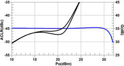
Figure 3 Output performance of a typical LTE downlink power amplifier; ACLR (black traces) starts to increase significantly ~10 dB before gain (blue trace) compresses.
The next critical step is matching. For many PA applications, it is important to determine the optimal match for linearity for the output transistor. For an LTE downlink PA, it is best to use an optimal power match. Because the LTE downlink uses OFDMA, it has a peak to average power ratio of about 10 dB.5 The result is seen in Figure 3. ACLR starts to increase significantly above an output power of about 21 dBm. This is about 10 dB below the level where output power starts to compress heavily. Peaks in power 10 dB above the average cause the limiting nonlinearities. A similar effect can be found in an LTE uplink PA, but because it uses SC-FDMA, it is 2 to 3 dB less severe.6 To first order, maximizing output power is the key objective to achieve LTE downlink PA linearity, so an optimum power match is used for the output stage.
Modulation bandwidth also imposes requirements on matching and bias circuitry. The modulation bandwidth is up to 20 MHz. The key concern is baseband products at 20 MHz. The HBTs have very high gain at these low frequencies. Matching circuits and bias circuits need to incorporate filtering to minimize these low frequency products. Otherwise, the low frequency products will limit power amplifier linearity. The high gain of the HBTs at low frequencies can also cause instabilities. Care must be taken in designing low frequency filtering in the matching and bias circuits to avoid possible oscillations and spurious outputs.
Summary
We have provided some background on LTE, specifically the downlink, and what it means to the PA designer. The LTE downlink signal has a high modulation bandwidth with many orthogonal carriers. This results in very high PAPR, and drives the entire PA design. We have gone through many of the choices a PA designer must make in addressing LTE downlink requirements and provided a roadmap to complete a successful design. This illustrates how the next generation of LTE PA for access points is being developed. There are more complex design approaches that have been taken for the uplink, where DC power is critically limited.7 These too may find their way into access points in the future.
References
- "Cisco Visual Networking Index: Global Mobile Data Traffic Forecast Update, 2010-2015," Cisco White Paper, June 1, 2011.
- "Report: Netflix is Largest Source of Internet Traffic in North America," PC Magazine, May 17, 2011.
- "Measuring ACLR Performance in LTE Transmitters," Agilent Technologies Application Note, January 7, 2010.
- "LTE, Evolved Universal Terrestrial Radio Access, User Equipment Radio Transmission and Reception," Technical Specification - ETSI TS 136 101 v9.1.0.
- B. Kim, J. Moon and I. Kim, "Efficiently Amplified," Microwave Magazine, August 2010, pp. 87-100.
- L. de Temino, G. Bernrdinelli, S. Frattasi, K. Pajukoski and P. Morgensen, "Single-User MIMO for LTE-A Uplink: Performance Evaluation of OFDMA vs. SC-FDMA," 2009 Radio and Wireless Symposium Digest, pp. 304-307.
- "RFMD PowerSmart Platforms Achieve 4G Performance Milestone," Microwave Journal, January 2011.