
Multiple-In, Multiple-Out (MIMO) antenna techniques promise to deliver exceptionally high data rates over new wireless technologies such as LTE and LTE-Advanced. However, the increase in attainable data rates brought about by MIMO technology is based on taking advantage of several channel characteristics that were inconsequential to legacy technologies. These new receiver designs necessitate changes in the way base stations and devices are tested, specifically a new test technique called MIMO Over-the-Air (MIMO-OTA) testing. Spirent’s new MIMO-OTA Environment Builder was designed to take the uncertainty and guesswork out of this otherwise intricate field of testing (see Figure 1).
Figure 1 MIMO OTA Environment Builder simplifies control over complex MIMO OTA testing.
MIMO OTA: What and Why?
MIMO operation is based on the idea that a set of receiving antennas can distinguish between separate data streams transmitted in the same frequency band as long as there is some spatial (directional) difference in the routes taken from transmitting antennas to receiving antennas. The simplest way to ensure that these differences are significant would be to separate the receiving antennas by large distances and ensure that the device antennas were arranged in a linear array that remains parallel to the linear array of transmitting antennas.
Of course, neither is feasible in a pocket-sized mobile device, requiring some clever work on the part of the antenna designer. Conducted-signal testing is still quite useful, but it fails to account for MIMO’s dependence on the physical antenna design. This is why radiated OTA testing has become critical with the increased reliance on MIMO techniques.
A typical MIMO OTA test consists of a shielded chamber, a signal source, a channel emulator and a number of transmitting antennas installed within the chamber. The chamber itself is one of two types:
- An anechoic chamber, which takes the chamber out of the equation by ensuring that RF energy from the antennas are not reflected into the field seen by the DUT.
- A reverb chamber, which not only uses reflections from the chamber walls, but augments and affects them with mechanically controlled reflective “stirrers” or “paddles”.
The two chamber-based methods each have pros and cons, and have driven intense study and discussion within the industry’s standards bodies. The Third Generation Partnership Project (3GPP), a group chartered to define wireless technologies and ensure their effectiveness, has devoted countless hours to the consideration of these methods. Discussions so far seem to indicate that while the anechoic chamber method offers greater resolution of the many variables that affect reception, the reverb chamber method is an acceptable, more cost-effective solution.
MIMO OTA: How?
To understand the effectiveness of the MIMO OTA Environment Builder, it is important to get a feel for the complexity of the channel models that need to be created for MIMO-OTA testing. Taking the anechoic-chamber case as an example, one set of channel models that are appropriate for MIMO OTA are the 3GPP’s Spatial Channel Models (SCM) (3GPP TR 25.996, “Spatial Channel Model For MIMO Simulations,” version 6.1.0, September 2003). In order to recreate the SCM over the air, the radiated signals to the device must maintain a number of properly matched statistical properties.
First, it is important to match the spatial correlation properties of the channel. The SCM is defined in terms of 20 specular components. One obvious approach to matching the SCM model is to reproduce these components using 20 separate antennas. This is not practical considering that the SCM actually contains many reflecting clusters, each consisting of 20 specular components. In addition, a fully realistic model needs to accurately represent the angle spread of the transmitted signal as well as the angles of arrival (AoA) seen by the device being tested.
Spirent research (3GPP R4-094673, “Evaluating Channel Models for MIMO OTA,” Spirent Communications, November 2009) has indicated that it is possible to fully match these spatial correlation properties of the SCM model with as few as three antennas per reflecting cluster. Remarkably, careful control of the powers transmitted can accurately reproduce all the correlation properties as well as the angular spread and angles of arrival of the SCM modeled signals. Additionally, Spirent research has shown that each transmit antenna in the chamber can be used to contribute signal content for the multiple reflecting clusters that make up the SCM model. The result of this work is a patent application regarding how a few antennas can accurately replicate a full field for MIMO OTA testing (International Patent Application no. PCT/US2010/024204, Publication no. WO/2010/094000). While this simplification dramatically reduces the number of antennas required in the chamber, making the anechoic chamber OTA method feasible, it also creates other complications.
The time-domain characteristics of the signal must also match the SCM. In particular, the signal received by the mobile must have the same level-crossing rate or “fading rate” as the SCM model. This becomes challenging because of the limited number of antennas used in the chamber. However, by using Spirent’s SR5500 Wireless Channel Emulator to create well-controlled faded signals into each transmit antenna, Spirent’s solution simultaneously matches both the correlation properties and the time-domain statistics of the Spatial Channel Model.
Another critical aspect of the channel model is the Doppler spectrum. Since the chamber approach is based on a reduced number of antennas, the combination of generated signals must be considered in composite and shown to have a Doppler spectrum resembling the target model.
Finally, many devices have particularly good polarization diversity. In order to generate an accurate radiated SCM for these devices, both the vertical and horizontal aspects of polarization must be modeled and matched to the SCM reference model. While accounting for the addition of multiple vertically polarized antennas is straightforward, combining horizontally polarized signals is much more complex.

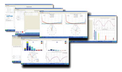
Figure 2 Control interfaces to MIMO OTA Environment Builder: Receiver control (upper left), transmitter control (upper right) and real-time in-test editing (bottom).
MIMO OTA Environment Builder
Spirent’s MIMO OTA Environment Builder offers an efficient interface designed to shield the user from the labor-intensive mathematical exercises required to create valid radiated models in an anechoic chamber (see Figure 2). Controlling the radiated environment requires three steps:
- Setting up the channel model parameters – setup can be as simple as selecting a standard channel model from a drop-down box, then entering mobility and other parameters. Customized channel models are also possible.
- Describing the in-chamber transmitting hardware – probe-specific parameters are selected here. Greater accuracy is achieved by a one-time chamber calibration that tells the software how to account for radiated path loss, etc.
- In-test editing – during test execution, screen-oriented controls can dynamically adjust parameters in order to quickly see the effects of realistic variations in the environment. For example, angles of departure and arrival can be edited, as can the total signal power seen by the device under test. On-screen graphics offer immediate feedback, helping minimize the potential for user error.
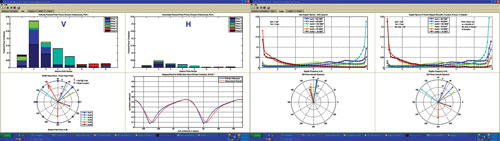
Figure 3 Graphical feedback from MIMO OTA Environment Builder.
The feedback mechanism designed into the tool offers comprehensive graphical summaries of the effects of the modeled channel. Figure 3 includes two of the tab views available from the tool. The left side of the figure shows per-probe values of power distribution related to both the vertical and horizontal polarizations. It also contains (on the bottom left) a polar summary of the power angle profile for the given model overlaid on a representation of the actual antenna probes as configured in the chamber. The graphic to the right of this polar plot is a map of the generated channel correlation as compared to the ideal narrow-band model. The two plots on the upper right-hand side of Figure 3 depict the ideal and generated Doppler spectra, while the two on the bottom show the power azimuth spectra at both the base station and the device under test.
The MIMO OTA Environment Builder is the latest manifestation of Spirent’s continuing strategic initiative to bring simplified control over complex wireless testing. This powerful tool offers straightforward, graphical control and feedback over the extremely useful but complex processing required to perform MIMO OTA testing with confidence. The implementation of MIMO-based 4G technologies promises great benefits. This potential underscores the importance of validating the entire MIMO channel, especially those elements that take on new significance with MIMO. When properly implemented, MIMO OTA testing can have a direct effect on the ability of operators and device manufacturers to deliver the data speeds promised by these advanced technologies.
Spirent Communications,
Sunnyvale, CA
(408) 752-7100
www.spirent.com
“With the onset of multi-antenna, multi-band devices in ever-shrinking form factors, optimizing OTA performance is critical to the success of LTE,” said Rob Van Brunt, Vice President of Spirent’s Wireless group. “Spirent’s test experts are leading the industry in developing a range of new MIMO OTA test methodologies, including techniques that use anechoic and reverberation chambers.”