
Wireless communication systems, such as cellular mobile communication systems, wireless local area networks (WLAN) and short-range communication systems (Bluetooth), provide convenient communication services in modern society. In an airplane, when the onboard wireless communication services are provided, many other systems may be used simultaneously. Compact equipment that supports multimode/multiband wireless systems is very attractive. As a result, a multimode/multiband system is becoming a focus issue for miniaturization and simplicity. Highly integrated multiband components such as antennas and filters are becoming important under this kind of trend. As a key component in the communication system mentioned above, multiple bandstop filters (MBSF) play an important role in weakening the interference among communication systems, due to coexisting narrowband applications.
Various topologies have been proposed and developed to realize filters with multiple stopband responses.1-7 Shaman and Hong describe a general configuration for cross-coupled wideband bandstop filters, based on an n-stub optimum bandstop filter with cross-coupling between the I/O feed lines.1 Microstrip BSFs using shunt open stubs and spurlines have been described.2 The concept of integrating bandstop filters into a conventional bandstop or bandpass filter has been proposed.3 K.S. Chin implemented two parallel-connected different-length open stubs for resonating at dual anti-resonance frequencies to realize a dual-band bandstop filter.4 Y.H. Jeng proposed a distributed perturbation scheme of the ring resonator with no need of extra stubs or notches.11 In this article, a novel structure of a MBSF with compact size is proposed, in order to protect an airplane navigation system from interfering signals generated by wireless access systems. The concept of the proposed filters is validated both by simulations and experiments.

Figure 1 MBSF configuration: (a) basic structure and (b) photograph of the fabricated triple-band MBSF.
Design of a Multiband Bandstop Filter
Generally, the bandwidth of a wireless access communication system ranges from 2.4 to 2.5 GHz or 5.0 to 5.8 GHz. In order to suppress interference with the aircraft navigation system, multiple stopbands should be available at special frequencies. More resonance cells could be employed, but the size of the circuit would inevitably increase. To overcome the problem, as shown in Figure 1, a novel configuration of a MBSF, with a size of 4 × 1 mm, is proposed. It consists of a cell of Y-axis symmetrical spurlines and the combination of a section of coupled lines and a rectangular ring resonator. The pair of Y-axis symmetrical spurlines was implemented to define the center frequency of the second stopband of the MBSF, while the ring resonator introduces the other two desired stopbands. Built on a 0.508 mm thick F4BK (ε = 2.65) substrate, three stopbands of the filter are designed within 2.38 to 2.45, 3.64 to 3.71 and 5.15 to 5.40 GHz. The simulation is performed with the commercial full-wave electromagnetic simulator HFSS.11.
Y-axis Symmetrical Asymmetrical Spurline
A basic spurline bandstop filter, consisting of two identical parallel conductors built in stripline configuration, was first introduced by Schiffman and Matthaei. Later, the analysis of spurline filters, using two asymmetrical lines, was proposed by C. Nguyen and K. Chang.8 In this article, a structure based on two-dimensional (Y-axis symmetrical), two asymmetrical lines was implemented, as shown in the Figure. The principal advantages of the asymmetric two-line filter are its ability to act as a symmetrical two-line filter combined with an impedance transformer, and can be designed to achieve a wider bandwidth by choosing appropriate dimensions for the asymmetric coupled lines.

Figure 2 Simulated frequency responses of Y-axis symmetrical spurlines.

Figure 3 Magnitude of S21 as a function of Wr.
Figure 2 compares the return loss and the transmission response between a conventional spurline and the Y-axis symmetrical spurline. The latter has a deeper rejection level of 48 dB and its bandwidth is twice that of a conventional filter. Furthermore, the bandwidth varies with the parameter Wt, while the other parameters are fixed. Figure 3 plots the simulated magnitude of S21 for various Wt. As Wt increases, the bandwidth of the bandstop filter widens.

Figure 4 Diagram of the ring resonator.
Mode Perturbation
Based on the theory that a uniform ring resonator fed by an asymmetric arrangement of feeding lines or that the circuit profile is perturbed, the degenerate modes become coupled, resulting in a narrowband bandpass response.9 A novel structure of a rectangular ring resonator is adopted to achieve the same effect as adding single or multiple open stubs. Figure 4 shows the schematic diagram of the ring resonator. The characteristic impedances of the coupled line and the rectangular ring resonator are Z2 and Z1, respectively. For odd-mode excitation, the output feed line is coupled to a position of zero electric field along the ring resonator and shows a short circuit. Therefore, no energy is extracted from the ring resonator and the ring circuit provides a stopband.10 The resonance conditions are determined by one of the following equations;11 the impedance ratio Z2 / Z1 is equal to R. There are some solutions for resonance, which are dependent on the combination of R and θ


Figure 5 Current vectors and electric fields distribution.
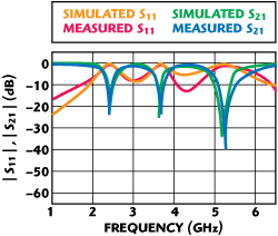
Figure 6 Simulated and measured S-parameter of the triple andstop filter.
Multiband Bandstop Filter Realization
Case 1: R = 1 and θ1 ≈ θ2
The optimized dimensions of the parameters are L = 32 mm, Wg = 0.2 mm, Wt = 0.2 mm, Lt = 6.6 mm, Wr = 2 mm, Lr = 4.1 mm and Ws = 1.4 mm for a 50 Ω line. Ls is chosen as 4 mm for convenience of measurement. The rectangular ring resonator has three attenuation poles, which are 2.41 GHz with 22 dB rejection, 3.61 GHz with 20 dB rejection and 5.17 GHz with 34 dB rejection. The distribution diagrams of current vectors and electric fields are described in Figure 5, at the center frequencies (f1, f2, f3) of the three stopbands. The total length of the ring is equal to quarter-wavelength, half-wavelength and three quarter-wavelength {2 × (θ1 + θ2) = λ/4, 2λ/4, 3λ/4} separately. θ1 and θ2 are the electrical lengths corresponding to the physical lengths l1 and l2. At the center frequency (f1) of the first stopband, the frequency response exhibits the characteristic of a series resonance and the direction of the current remains unchanged in the range of [0, π]. At the center frequency (f2) of the second stopband, the surface currents of the microstrip circuits around the ring resonator and the exciting mode shows the character of a direct connection (λ/2 transmission line), while at the frequency (f3) of the third stopband, the frequency response shows the characteristic of a parallel resonance. The direction reverses as the phase goes through π/2. The simulated and measured amplitude responses of the triple bandstop filter are shown in Figure 6. It is concluded that the rejections of the ring resonator filter are greater than 20 dB within 2.38 to 2.46 GHz, 3.63 to 3.72 GHz and 5.17 to 5.41 GHz, respectively. The measured results are even better than the simulated ones.
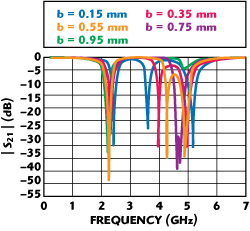
Figure 7 Simulated S21 of the ring resonator for various width b.

Figure 8 Return and transmission loss of the dual-band filter: (a) simulated and (b) measured.
Case 2: R<1 and θ1 ≈ θ2
As the width of the rectangular ring (b) increases, the degenerate modes, which can be activated as transmission zeros at the frequencies of 3.6 and 5.2 GHz, exhibit a gradually concentrated trend. Investigating the results exhibited in Figure 7, the two attenuation poles, starting from the center frequencies, move together and form a wider stopband. When b is equal to 0.75 mm, the corresponding impedance ratio R is equal to 0.56. Figure 8 shows the simulated and measured results of this filter. The proposed filter has two stopbands at 2.14 to 2.24 GHz with 15 dB rejection, and 4.60 to 4.78 GHz with 30 dB rejection, an insertion loss lower than 0.4 dB and an attenuation rate for the sharp cut-off frequency responses of 175 dB/GHz (calculated from 4.35 GHz with -1 dB to 4.63 GHz with -50 dB) and 131.3 dB/GHz (calculated from 1.88 GHz with -1.88 dB to 2.19 GHz with -42.6 dB).
Conclusion
A compact and sharp rejection multiband bandstop filter has been proposed, which is composed of a cell of a spurline bandstop filter and a single ring resonator to achieve multiple stopbands. The measured results match the simulated prediction. The proposed MBSF shows a much deeper rejection and wider stopband without increasing the circuit size. The new filters were designed to weaken the interference among communication systems due to coexisting narrowband applications, especially in an aircraft flight system.
References
- H. Shaman and J.S. Hong, “Wideband Bandstop Filter with Cross-coupling,” IEEE Transactions on Microwave Theory and Techniques, Vol. 55, No. 8, August 2007, pp. 1780-1785.
- W.H. Tu and K. Chang, “Compact Microstrip Bandstop Filter Using Open Stub and Spurline,” IEEE Microwave and Wireless Components Letters, Vol. 15, No. 4, April 2005, pp. 268-270.
- W.H. Tu and K. Chang, “Compact Second Harmonic-suppressed Bandstop and Bandpass Filters Using Open Stubs,” IEEE Transactions on Microwave Theory and Techniques, Vol. 54, No. 6, June 2006, pp. 2497-2502.
- K.S. Chin, J.H. Yeh and S.H. Chao, “Compact Dual-band Bandstop Filters Using Stepped-impedance Resonators,” IEEE Microwave and Wireless Components Letters, Vol. 17, No. 12, December 2007, pp. 849-851.
- R. Levy, R.V. Snyder and S.H. Shin, “Bandstop Filters with Extended Upper Passbands,” IEEE Transactions on Microwave Theory and Techniques, Vol. 54, No. 6, June 2006, pp. 2503-2515.
- R.Y. Yang, M.H. Weng, C.Y. Hung, H.J. Chen and M.P. Houng, “Novel Compact Microstrip Interdigital Bandstop Filters,” IEEE Transactions on Ultrasonics, Ferroelectrics and Frequency Control, Vol. 51, No. 8, August 2004, pp. 1022-1025.
- M.Y. Hsieh and S.M. Wang, “Compact and Wideband Microstrip Bandstop Filter,” IEEE Microwave and Wireless Components Letters, Vol. 15, No.7, July 2005, pp. 472-474.
- C. Nguyen and K. Chang, “On the Analysis and Design of Spurline Bandstop Filters,” IEEE Transactions on Microwave Theory and Techniques, Vol. 33, No. 12, December 1985, pp. 1416-1421.
- I. Wolff, “Microstrip Bandpass Filter Using Degenerate Modes of a Microstrip Ring Resonator,” Electronics Letters, Vol. 8, No. 12, June 1972, pp. 302-303.
- D.K. Paul, P. Gardner and K.P. Tan, “Suppression of Even Modes in Microstrip Ring Resonators,” Electronics Letters, Vol. 30, No. 30, October 1994, pp. 1772-1774.
- Y.H. Jeng, S.F.R. Chang, Y.M. Chen and Y.J. Huang, “A Novel Self-coupled Dual-mode Ring Resonator and Its Applications to Bandpass Filters,” IEEE Transactions on Microwave Theory and Techniques, Vol. 54, No. 5, May 2006, pp. 2146-2152.
Yanwei Wang received his BS degree in electronic engineering and optoelectronic techniques from Nanjing University of Science and Technology, Nanjing, China. He is currently working toward his PhD degree at Southeast University, Nanjing, China. His research interests include RF front-ends for mobile communications.
Jianyi Zhou received his BS, MS and PhD degrees from Southeast University, Nanjing, China, in 1993, 1996 and 2001, respectively, all in radio engineering. Since 1996, he has been with the State Key Laboratory of Millimeter Waves, Southeast University, where he is currently an associate professor. He has been engaged in numerical methods for electromagnetic problems and RF front-ends for mobile communications.
Wei Hong received his BS degree from the Zhenzhou Institute of Technology, Zhenzhou, China, in 1982, and his MS and PhD degrees from Southeast University, Nanjing, China, in 1985 and 1988, respectively, all in radio engineering. Since 1988, he has been with the State Key Laboratory of Millimeter Waves, Southeast University, where he is currently a professor and the associate dean of the Department of Radio Engineering. He has been engaged in numerical methods for electromagnetic (EM) problems, millimeter-wave theory and technology, antennas, EM scattering, inverse scattering and propagation, RF front-ends for mobile communications and the parameters extraction of interconnects in very large scale integration (VLSI) circuits.