In a previous publication,1 the author introduced a new dual-ridge horn that corrected the pattern problems of the traditional dual-ridge horn antenna.2 All the parameters of this new horn, shown in Figure 1, were measured and it was tested for use as an EMC immunity and emissions testing horn. It has also been tested for compact range illumination, showing a good performance in the low end of the frequency range and a small reduction in the diameter of the quiet zone (QZ) at the upper end. This horn was designed using MW Studio, a commercial package based on the finite integration time domain technique.
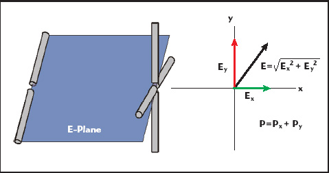
In this article, the concept of the new double-ridged-guide horn (DRGH) was taken to a higher level of versatility by creating a dual-polarized antenna. A dual-polarized antenna can measure both orthogonal field components simultaneously, which allows the engineer or technician to measure 3D patterns by rotating the antenna under test (AUT) in both azimuth and elevation. In addition, there is no need for an expensive rotational positioner to support the dual-polarized source antenna. The horn can be used in EMC compliance measurements. Since no mechanical rotation is necessary, the uncertainty in the measurement is reduced since the test set-up is left untouched for the different polarizations. If a dual-input receiver or an RF switch system is used, the test time can also be reduced. The importance of measuring 3D patterns is that the total radiated power (TRP) can be calculated by integration over the measured pattern. The TRP is one of the parameters of interest when performing an over-the-air test, per the CTIA standard. As the antenna under test is rotated, the orientation of the radiated field vector is not known. By measuring both principal polarizations simultaneously, the total E field vector can be obtained independently of the direction of the radiating object and the polarization of its field (see Figure 2). Consequently, a dual-polarized antenna is an integral part of a system used to measure the 3D patterns of antennas. In addition, there is a desire to use a broadband antenna to limit the number of measuring antenna changes in the system. The proposed horn provides these two characteristics. It is broad-banded, covering four octaves, and dual polarized.
The Numerical Model
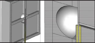
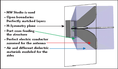
The design of the proposed horn started from the original DRGH design.1 It preserves the shape of the ridges used before, only slightly modified to be able to add a set of two more ridges in the orthogonal plane, as shown in Figure 3. The coaxial line feeding the antenna is also included in the numerical model. This provides a more accurate model than using a gap source between two opposite ridges. This approach, however, does require more unknowns for the model and therefore more memory. To use symmetry and reduce the memory requirements of the model, only one port is simulated. The other port is not introduced in the model. In the original design, it was found that the side structures of the traditional double-ridged horn affected the pattern by splitting the main beam. The model was set to have non-metallic sides with a relative permittivity of 2.5, the manufacturers’ claim for polycarbonate plastics. Figure 4 shows the new model with the plastic sides. The metallic part of the horn was simulated as a perfect electrical conductor (PEC) and the model was surrounded by a perfectly matched layer (PML). A plane of magnetic symmetry was used to reduce the computational domain in half. The final plastic-sided or open-boundary horn showed a good gain behavior and a fairly stable pattern for the upper half of the frequency range, the main beam remaining a single lobe for the entire range. The final design had overall dimensions of 6" by 6" aperture and approximately 6" in length.
Comparison Between Numerical and Measured Results
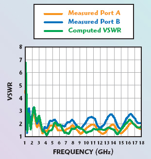
Once acceptable results for patterns and input parameters were obtained, three prototype antennas were manufactured. The prototype’s input parameters were measured and good agreement was found between the measurements and the model predictions. However, when measuring the pattern, it was discovered that, at the upper edge of the frequency range, the polycarbonate sides had an effect on the pattern behavior. The presence of the polycarbonate sides was causing the pattern to split at different frequencies. This was not fully predicted by the model. One possibility is that, since only 10 cells per wavelength were used at the highest frequency in the time domain method approach, there is not enough accuracy in the predictions. A second possibility is that the dielectric permittivity was an approximation. The model used a constant value for the 2 to 18 GHz range. The actual material may have a frequency dependent permittivity that caused the unpredictable effects at the upper range. Figure 5 shows the pattern with and without the plastic sides at 18 GHz. The numerical model was modified to take away the sides. Also, the sides on the prototypes were removed and the final horn design has no sides that can cause perturbation to the pattern. Figure 6 shows the horn model without the sides. A flange was added to the horn feed cavity. The purpose of this flange is to attach the horn to the shield of the anechoic chamber keeping the cables outside the enclosure when measuring patterns. This same flange was added to the prototypes. Figure 7 shows the VSWR for the computed port and for the ports of the prototype antenna without the sides.
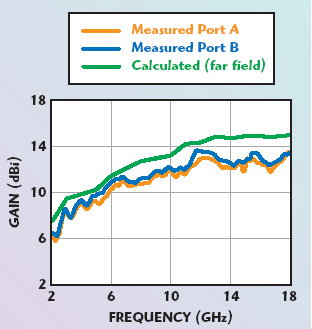
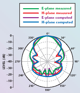
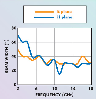
The gain of the prototype horn was measured at 1 m, using the SAE ARP 958 revision C standard approach. Because that standard calls for the measurement to be done at 1 m from the face of the horn, it is the near field gain that is reported. This may explain the slight difference with respect to the computed results. There is still a very good agreement between the predictions and the measurements, as shown in Figure 8. The pattern was measured in a fully anechoic chamber at different frequencies. Figures 9 to 13 show the comparison between the model predictions and the measured results for different frequencies. Very good agreement between the predicted and measured results can be seen in the figures. The difference is never larger than 2.5 dB between prediction and measurement in the front lobe. In the back lobes area, the differences can be larger. It may be caused by the positioning equipment that supports the antenna. Although built of non-metallic materials, it may still block the radiation from the antenna during the measurement. In addition, as in the case of the 18 GHz measurements, the difference in the back lobes is caused by the measuring system running into the noise floor of the equipment. In all the cases shown, the model accurately predicted the position of the first null and the levels of the side lobes. Figure 14 shows the final configuration of the horn. No sides enclose the ridges. Because of this lack of sides, the ‘open-boundary ridged horn’ name was coined to describe this type of antenna. Additional measurements were performed on the antenna. The 3 dB beamwidth and the front-to-back ratio were obtained from the pattern measurements. Figure 15 shows the 3 dB or half-power beamwidth for the new design. Figure 16 shows the front to back ratio. Since the numerical model only contained one port and coaxial feed, one of the parameters that could not be predicted during the modeling phase was the cross-port isolation. The cross-port isolation is a limiting factor on the cross-polarization isolation of the antenna. It is obtained from an S21 parameter measurement, where a signal is injected into one port and the output on the orthogonal port is measured. Figure 17 shows that the cross-port isolation is higher than 25 dB over the whole frequency range.

Conclusion
This article has presented a new quad-ridge horn antenna design without sides. This “open-boundary” horn has shown a stable pattern for the upper half of the frequency range as can be seen from the flatness of the gain and the 3 dB beamwidth. The resulting antenna is intended for use in anechoic chambers to measure the patterns of other antennas. Since the antenna covers multiple octaves, it is possible to measure a large variety of antennas without changing the measuring antenna in the chamber. In addition, the antenna can be used as a broadband antenna in EMC emissions measurements. Future work must be done in testing the potential of the antenna as a source in tapered chambers to see its capabilities. The potential for its use in compact ranges should also be studied.
Acknowledgments
The author wishes to thank the Calibration Laboratory staff at ETS-Lindgren for their help in obtaining data for this article and especially Leon Enriquez for the numerous measurements of the 3D patterns of the prototypes during the developmental work.
References
1. V. Rodríguez, “New Broadband EMC Double-ridge Guide Horn Antenna,” RF Design, Vol. 27, No. 5, May 2004, pp. 44–50.
2. C. Burns, P. Leuchtmann and R. Vahldieck, “Analysis and Simulation of a 1 to 18 GHz Broadband Double-ridged Horn Antenna,” IEEE Transactions on Electromagnetic Compatibility, Vol. 45, No. 1, February 2003, pp. 55–60.

Vicente Rodríguez received his BSEE, MS and PhD degrees from the University of Mississippi in 1994, 1996 and 1999, respectively. He joined the department of electrical engineering and computer science at Texas A&M University-Kingsville (formerly Texas A&I University) as a visiting assistant professor in 1999. In June 2000 he joined EMC Test Systems (now ETS-Lindgren), where he is currently the senior principal antenna design engineer in charge of the development of new antennas for different applications and on improving the existing antenna line. His interests include numerical methods in electromagnetics, especially when applied to antenna design and analysis. He is the author of more than twenty publications including journal and conference papers as well as book chapters. He holds patents for hybrid absorber design and for a new dual-ridge horn antenna design for EMC applications.