
Semi-rigid cables have long been the backbone of the US Military interconnection technology for RF and microwave applications. These cables provide a robust means of interconnection supporting high power, low loss and high frequency applications with extremly good shielding characteristics. With no fear of sand and abrasion, these cables provide armor to military electronics on land, sea and air. Today, however, is semi-rigid really the best solution for high reliability?
San-tron believes that Times Microwave has developed an ideal alternative to semi-rigid cables that should be seriously considered for system integrations. Below is a discussion of the apparent differentials that Times TFLEX-402 and TFLEX-405 provide to technical performance, costs of design-in, cost of manufacturing, and to the logistics chain and maintenance operations. This is followed by a discussion of the connector designs that fully leverage the capabilities of flexible cables.
Technical Attributes & Differentials
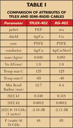
The technical performance of semi-rigid cables and TFLEX are extremely similar. A brief decision matrix is helpful in identifying the major characteristics. Due to the solid copper outer shield of semirigid cable, these assemblies are superior at diffusing heat, insuring low attenuation and thus providing higher power handling abilities. The TFLEX series provides better support for corrosive environments due to its FEP jacket and silver clad metals. TFLEX also supports low attenuation, full shielding and further offers multiple cable bending. Table 1 provides a close look at some of these differentials in attributes.
The standard semi-rigid RG-402 cable is composed of a solid copper shield and a silver clad steel center conductor. Thus, the operating environment needs to be considered in choosing these materials. Will the assembly be exposed to corrosive agents that will attack the copper shield? Will the steel center conductor generate PIM products within frequencies of interest? This cable does support tight bend radii of 6.4 mm; however, the cable can only be bent once. Repeated bending will fracture the solid copper shield.
TFLEX cables are composed of a FEP jacket and silver clad copper metals. The FEP jacket provides excellent protection from corrosive environments. This TFLEX shielding is a composite of a helical wrap and braid, and like semi-rigid, the RF leakage is beyond the range of measurable limits. The silver clad helical wrap further provides temperature phase stability, loss stability and low insertion loss. A one meter length of the two cables perform within 0.05 dB of each other at 18 GHz. From the technical profile of these cables, the only parameter that favors semi-rigid cable is power handling; at 18 GHz the semi-rigid nudges out TFLEX at 65 versus 48 W.
Costs of Design-in
Within system integration, each semi-rigid cable requires predetermined geometries. Just as a civil engineer designs bridges, entrance ramps and clover leafs into our highways, a mechanical engineer takes on the task of designing bend radii, segment lengths, over and under locations, etc. Each cable becomes a customized part number with exacting requirements to rigidly lie within the constraints of various barriers: amplifiers, filters, mixers and other cables. When subsystems are modified and upgraded, so too are the cable assemblies, which effects fit, form and function between new versus legacy deployments. With the typical semi-rigid cable being composed of ~5 bends and total lengths of 8 to 30 inches, a simple problem just became a documentation dilemma. All of these custom cables can be supported with standard TFLEX assemblies supplied in incremental lengths. One can simplify the documentation and focus on engineering creativity and solving technical issues.

Costs of Manufacturing
The manufacturing processes for semi-rigid is a bit more involved than the TFLEX methodology. Below is a cost comparison just in the required capital equipment for both processes (see Table 2).
To manufacture semi-rigid cables there is a common process requiring $77,300 in estimated costs:
- Cable is supplied in straight 8-foot lengths
- Cut the cable to developed length
- Process the cable through a bending machine
- Verify position of bends within tolerances via a quad-axis machine
- Thermal cycle the cable to relieve stresses within the PTFE core
- Strip the cable ends for connector termination
- Solder both the center contacts and bodies to the cab
- Comparatively, the process for TFLEX only requires $18,400 of costs:
- Cable is supplied in continuous spools
- Cut the cable to developed length
- Strip the cable ends for connector termination
- Solder bodies to the cable
Effects on Logistics & Maintenance
Imagine all the costs associated with producing these unique semi-rigid cable assemblies and every dimension is within specification; every segment length, every bend radius, and even the tolerance stack-up from connector end to connector end has been minimized. These cables are not simply going into a plastic bag and shipped to the customer. Each cable assembly part number will have unique cut foam inserts and these cables will be carefully placed into expensive custom boxes. Then a set of these boxes will be placed into a larger shipping box. If the customer requires five different cables for a deployment then the manufacturer will provide five different sets of cut foam inserts. Each assembly will be custom packaged to prevent dimensional changes during shipping and handling.
The customer will receive different crates of semi-rigid cable assemblies with each assembly packaged in a box that measures 12" × 18" × 6". How do they place these crates within your work flow? And how quickly can they remove the empty boxes from the production floor and store or dispose of them?
The alternative could be as simple as a couple of cable lengths of TFLEX supporting all of the semi-rigid applications. Then just a couple of part numbers of flexible TFLEX cables are needed. These are bulk package as 20 pieces into a plain plastic bag and dropped into the mail. No need for foam inserts, pallets, specialized work flow and packaging removal.
For maintenance operations this advantage is greatly multiplied. Consider TFLEX to be the “duck tape” of the 21st century for microwave applications. Regardless of the OEM, the frequency range and the performance parameters, standard lengths of TFLEX cable assemblies can be stocked for a full array of upkeep and retrofits. The concern is shifted from exacting geometries to only the need for minimum length assemblies. And with the minimum of tooling required it is even possible to produce retrofit cable assemblies on site.
eSERIES: Connector Designs that Leverage Flexibility
Now that TFLEX cable has been offered as a drop-in substitute for semi-rigid cables, there is a need to take a look at connectorization. What attributes can the connector bring to the overall reliability and performance of these assemblies?

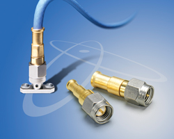
Figure 1 e Series improvements made to SMA connector.
The San-tron eSERIES product line was initiated with the SMA interface as this is the most prevalent connector for intra-system integrations, the connection of sub-systems within an OEM package. The company wanted to design advance features into the connector to remedy issues that were common with conformable cable assemblies. By combining experiences of both semi-rigid and conformable cable assemblies, the new eSERIES is a positive step in the enhancement of performance and survivability in the field. The following features were implemented into the eSMA series (see Figure 1):
- Enhanced coupling nuts that will not “walk-off” brass bodied connectors
- Captivated factory-set center contacts for no worry interface dimensions
- EZ style, solder free center contacts
- Integral positive cable stops that control RF structure and limits solder contamination
- Rigid cable support beyond the solder wick line
- Cable assembly performance with VSWR < 1.22 (DC-20 GHz)
- PIM performance < -150 dBc
The enhanced coupling nut is a far reaching improvement beyond the e-SERIES product line. It is a natural occurrence that brass bodied SMAs coin with each successive torque application of the coupling nut. As this coining continues to progress, the retaining ring eventually fails to capture both the body and the coupling nut. The brass SMA connectors have implemented a feature that prevents this failure mode. All of these SMA connectors exceed the military specification of 15 in-lbs of coupling proof torque. It typically requires ~80 in-lbs of torque to cause fracture. The captivated, factory-set center contacts provide controlled interface dimensions that reduce the opportunity for mechanical collisions within mating connectors.
The EZ style, solder free contacts prevent heat disruption of the core dielectric helping to maintain the 50 ohm structure. It is the combination of heat disruption and controlled solder spacing of the center contact that contributes most to variation in RF performance. These EZ style contacts negate these limitations.
Integral positive cable stops control the resultant geometry of the prepared cable into the connector. The cable stop also limits the flow of solder to the braided cable zone preventing solder flow forward into the connector cavity. This helps give the cable assembly technician a repeatable process to support the higher 20 GHz performance.
As solder is applied to the cable it naturally wicks up the cable braid. The further it wicks, the more problems that will ensue. The wick line is a very distinct characteristic in that the braid is solid on one side of the line and is flexible on the other. Thus, this wick line becomes a fulcrum plane at which cable failure is prone. By controlling heat and dwell time it is easy to limit this solder wicking to 0.33 inches. Then the application of the optional crimp ferrule provides mechanical support to 0.49 inches. This extended ferrule provides the mechanical support that prevents braid failure under multiple cable flexing. Additional support can then be augmented with heat shrink strain relief.
The ultimate goal of these enhancements is to provide a consistent, reproducible process to fabricate low cost SMA cable assemblies with strong RF performance through 20 GHz. As a result, the required skill set of the cable assembly technician has been simplified. These features with 20 GHz performance were implemented into SMA plugs, jacks, panel mounted jacks and weather sealed bulkhead mounted jacks. Recently the SMA right angle plug was added to this product line with performance to 12.4 GHz.

The next series of solutions focused on inter-system integrations—how to get the signals to the outside world. The type N and 7/16 connectors have a strong market position for external connectivity. Therefore, these features were implemented into an 18 GHz type N bulkhead mounted jack and into an 8 GHz 7/16 panel jack and bulkhead mounted jack. The RPTNC and RPSMA were also added specifically for wireless LAN customers. The product offering of eSERIES for TFLEX-402 is shown in Table 3.
Re-thinking the use of high performance flexible cable and connector designs shows that semi-rigid cables may not be the best choice in many demanding applications. The traditional semi-rigid cables may actually be increasing manufacturing costs, reducing design flexibility, increasing maintenance costs and impacting operational costs that could be avoided in many cases with flexible cable options.