
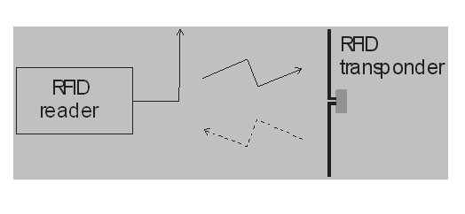
Figure 1 Reader-Transponder-reader link in the passive UHF RFID system.
Radio frequency identification (RFID) is an automatic wireless technology for data transfer developed in the 1970s. This technology has been developing in recent years and has become popular in many service industries, purchasing and distribution logistics, industry, manufacturing companies and material flow systems. It also provides information about people, animals, goods and products in transit, etc. There are several standards that regulate the use of RFID systems depending on the region (ISO, Class 0, Class 1 and Gen 2);1 thus, for UHF RFID systems, the frequency range is divided into subranges: 866 to 869 MHz (Europe), 902 to 928 MHz (America) and 950 to 956 MHz (Asia).
RFID systems consist of two components: the reader and the transponder (or tag), as shown in Figure 1. There are two main classes of RFID systems, depending on the characteristics of the transponder: active or passive. Passive RFID systems, which are more frequent, use the electromagnetic field of the reader for their operation, because the passive transponders do not have their own power supply. Active transponders incorporate a battery, which supplies all or part of the power for the operation.
In digital data transmission between the reader and the transponder, in a full duplex system, the following three types of modulation are mostly used:
Due to its simple demodulation, ASK is commonly used.
The features of any wireless system, including RFID, depend highly on the characteristics of the antenna (a) and the propagation channel (b).2
(a) Operating frequency, gain characteristics (maximum gain, radiation pattern, beamwidth, etc.), matching (VSWR or return loss), polarization, sensitivity to nearby objects with different properties.
(b) Path loss, fading.
Depending on the wireless communication system, some of these characteristics may be more important factors in the design of RFID systems. Thus, operation of passive UHF RFID systems is based on modulation of the reflected RF wave or backscatter from the reader, that differs from modulations in traditional wireless systems, which comprise active transceivers on both sides of the link (802.11, Bluetooth, etc.).![]()
Passive Transponder: Basic Characteristics
A passive transponder consists of two main parts: the antenna and the application specific integrated circuit. All the energy needed for the operation of the microchip has to be provided from the RF signal received from the antenna. The information necessary for the identification of the object carrying the transponder is written in the ASIC chip. This digital information with precisely defined content and length is stored in an appropriate RAM and written in the ASIC chip memory. Hence, the modulated RF signal emitted from the reader’s antenna reaches the transponder’s antenna. Part of this energy is used for the transponder’s operation by changing its input impedance, according to the modulation information written in the ASIC chip. In the return link from the transponder to the reader, the incoming RF signal is backscattered from the transponder and a proportion of incoming power is returned to the reader’s antenna. The processing circuit of the transponder (ASIC) alters its RF impedance and controls the amount of the reflected field. In this case, modulation of the scattered field contains the identification information. The transponder is identified when the reflected field is received and decoded in the reader’s unit. The antennas play a crucial role in such a communication system; thus, great attention has to be paid to their design. Some of the main transponder antenna characteristics include:
- They must have dimensions small enough to be attached to the required object
- They must have omnidirectional or hemispherical radiation pattern
- They must provide the maximum possible signal to the ASIC
- They must have a polarization that matches the enquiry signal regardless of the physical orientation of the object
- They must be robust
- They must be inexpensive
Transponder Antenna Design
Two characteristics of the transponder antenna are especially important: the input impedance and the radiation pattern. The input impedance of the antenna has to be matched to the chip impedance; in other words, these two impedances have to be complex-conjugates. Most of the chips have the real part of their impedance approximately a few to several dozens of ohms and a capacitive imaginary part of approximately 100 to 1000 Ω. The antenna must have an impedance with a small real part and with an inductive imaginary part of relatively high value. It should be noted that it is very important to provide a good match between the antenna and the ASIC chip, in order to achieve, as efficiently as possible, the RF energy transmission from the antenna to the chip. The chip in passive RFID systems also uses this energy for its power supply.
The radiation pattern, as already mentioned, has to be omnidirectional. A dipole antenna fulfills this requirement relatively easily; it is usually used in various versions of RFID transponders. Dipoles have a simple structure, so antennas realized with them are not complex and therefore are convenient for in-series production.

Figure 2 Layout of the RFID antenna with a dipole with CPS and a rectangular loop.
For the realization of the antenna, a dipole with CPS matching has been chosen,3 which enables high values of inductive reactance. By changing its geometry, that is the length of the dipole arm (Ld) and the length of the matching CPS (Ls), it is easy to control both the real and imaginary part of the dipole’s input impedance. In order to achieve greater values of the inductive reactance, one more element—an inductively coupled rectangular loop—was also introduced that enables additional varying and controlling of the antenna’s input impedance. Figure 2 shows the layout of the designed antenna. By optimizing the loop’s length (Lp) and its distance from the feed line (h), the required value of the input impedance can be easily obtained.

Figure 3 Realized RFID antenna with the ASIC chip.
Realization of the RFID Antenna
The RFID antenna is designed for the ASIC chip input impedance of Zc = (20 - j127) Ω at 900 MHz (ALL-9238 from Alien Technology) and a dielectric substrate (Rogers RO4003C) (εr = 3.38, h = 0.2 mm). First, only the dipole was analyzed by varying its dimensions, using the program package for electromagnetic simulation. After satisfactory results (high values of inductive reactance and low values of resistance) were obtained, the complete antenna structure, together with an inductively coupled loop, was analyzed. The input antenna impedance attained by simulation is approximately (18 + j124) Ω at 900 MHz for the following antenna dimensions: Ld = 45 mm, Wd = 8 mm, L = 15 mm, Ls = 25 mm, h = 1.5 mm and Lp = 12 mm. The width of the feed line is 1 mm. Figure 3 shows the realized antenna with the ASIC chip.

Figure 4 Simulated real and imaginary parts of the antenna input impedance for various characteristic dimensions of the antenna.
Simulated and Measured Results
The analysis consisted of varying one of the characteristic dimensions at a time, while keeping the others constant, in order to obtain the required impedance value. The diagrams in Figure 4 show the results of the analysis. From the accomplished analysis, one can conclude that the rectangular loop’s length (Lp) as well as the distance from the feed line (h) have the most significant effect on the impedance variation. The simulated radiation patterns in the E- and H-planes are shown in Figure 5. The simulated gain of the antenna is 2.45 dBi. Due to the symmetrical input port and the significantly high inductive reactance, the particular problem concerning this antenna type is the input impedance measurement. One solution is to transform the symmetrical input to an asymmetrical one;4 the other is to use just one half of the antenna placed above a conducting grounded plane and thus obtain an asymmetrical input.5 The latter method is simpler and does not introduce additional losses. In this way, the measured impedance is equal to one half of the whole antenna impedance. The method of measuring one half of the antenna is shown in Figure 6.

Figure 5 Simulated E- and H-plane radiation patterns ofthe UHF RFID antenna.
The measured input impedance of the realized UHF RFID antenna at 900 MHz using the “one half method” is Za/2 = (10.6+j76.4) Ω (Za = (21.2+j152.8) Ω) and is shown in the Smith chart (see Figure 7). The measured real part of the impedance value deviates from the real part of the ASIC chip input impedance by 1.2 Ω; its imaginary part deviates from the corresponding part of the chip impedance by 25.8 Ω. This indicates good matching that promises low loss of RF energy. Verification of the whole system operation is carried out by measuring the reading distance of the reader-transponder (tag) system. It shows that this distance (measured in an office) is approximately 2 m. The antenna was placed on a cardboard box (object to identify). The overall dimensions of the box were 360 mm × 235 mm × 130 mm.

Figure 6 Measuring the UHF RFID antenna input impedance using a network analyzer.

Figure 7 Diagram of the measured half input impedance of the realized antenna in the range 0.8 to 1.0 GHz.
Conclusion
The realized and simulated6 UHF RFID antenna is characterized by a new and simple design as well as the electrical characteristics that completely satisfy standards of the RFID system. The antenna covers the entire UHF RFID band (Europe, America and Asia). Such simple design implies easy and low-cost manufacturing, especially when realized on inexpensive substrates (PET, PVC) by using screen printing.
This work is supported by the Serbian Ministry of Science and Technological Development.
References
- K. Finkenzeller, RFID Handbook, John Wiley & Sons Ltd., Chichester, UK, 2003.
- K.V.S. Rao, P.V. Nikitin and S.F. Lam, “Antenna Design for UHF RFID Tags: A Review and Protocol Application,’’ IEEE Transactions on Antennas and Propagation, Vol. 53, No. 12, December 2005, pp. 3870-3876.
- A. Nešic´, I. Radnovic´, M. Mikavica, S. Dragaš and M. Marjanovic´, “New Printed Antenna with Circular Polarization,’’ 1996 European Microwave Conference Proceedings, pp. 569-570.
- J.D. Griffin, G.D. Durgin, A. Haldi and B. Kippelen, “RF Tag Antenna Performance on Various Materials Using Radio Link Budgets,’’ IEEE Antennas and Wireless Propagation Letters, Vol. 5, No. 1, 2006, pp. 247-250.
- Y. Tikohov, Y. Kim and Y.H. Min, “Compact Low Cost Antenna for Passive RFID Transponder,’’ 2006 IEEE Antenna and Propagation Society International Symposium Digest, pp. 1015-1018.
- www.wipl-d.com