
RF identification (better known by the acronym RFID), while not a new technology, has experienced a recent resurgence due to new applications in the supply chain management, coupled with advances in the technology. The identification of an object using RF interrogation has been in use almost as long as radar but until recently the technology has not received much attention in the commercial sector due to the high cost of implementation. In the early 1990s, low cost inductively coupled tags saw mass deployment in applications such as access control. Today, UHF RFID is undergoing a revolution driven by the disruptive changes in technology, which are allowing low cost tag designs, and readers that are moving from cumbersome systems to integrated circuits. This has resulted in the passage of new standards, the assignment of global frequency bands in the UHF range and deployment of pilots worldwide.
RFID systems operate at several popular frequencies worldwide. Inductive loop systems operate at low frequency (LF) at either 125 or 134 kHz; HF systems operate worldwide at 13.56 MHz. Systems at these frequencies are very robust and insensitive to obstructions such as the human body. However, they are limited by the reach of the inductive loop and hence work to approximately 1 meter range. UHF systems are in the radiative domain and provide a much longer reach, typically 3 to 10 m for a passive tag and 100 m for an active or battery assisted tag. These systems operate in the ISM bands between 860 and 960 MHz and also at 2.4 GHz worldwide.
The RFID systems attracting the most industry attention recently are the passive backscatter systems operating in the UHF band. This is partially due to the efforts of EPC-Global to standardize the technology while simultaneously being driven by applications in supply chain management. In late 2003, Wal-Mart delivered a mandate to its top-100 suppliers, requiring them to provide RFID tags on all pallets and cases or cartons delivered to their distribution centers by January 2005. Other large retailers in the US such as Target and large European retailers such as Metro and Tesco joined Wal-Mart. In conjunction with these large retailers, the US Department of Defense (DoD) has initiated the adoption of UHF RFID, further fueling the commercial interest in this technology. The supply chain industry predicts that, as the cost of tags works its way down to just a few cents, billions of tags and millions of readers will be deployed, enabling identification of every mobile item. According to Venture Development Corp. (VDC), the $1.7 B global RFID market in 2004 will grow to $5.9 B in 2008. Such staggering growth will be fuelled both by the ratification of standards and technological breakthroughs at all levels of the RFID infrastructure.
The focus of this article is the challenge that faces the RF engineer in the RFID industry. Similar to the cellular phone industry in the late 1980s, the RFID infrastructure must evolve to reduce cost and size while adding network functionality and user driven applications. In the same manner that bulky mobile phones of yesteryear have become miniature personal computing devices, the coming years will see RFID readers reduced to inexpensive, ubiquitous network interface devices that are a part of our daily lives. As the reader technology becomes implemented in high density IC processes and the power consumption is reduced through new architectures, the readers will become fully mobile, resulting in new applications inconceivable beyond the supply chain.
RFID systems, whether passive, active or semi-passive, all consist of the same common components, a reader and a tag (see Figure 1). The tag memory contains data formatted to identify the object. The reader communicates with the tag to read and write data to and from the tag’s memory. The simplified block diagram of a tag shows its major components. The tag contains circuits to both rectify DC power from the incoming RF signal as well as to detect and extract the information modulated on the signal. The antenna load is a controlled resistance, illustrated as a transistor that changes the impedance of the dipole, enabling the backscatter. The backscatter technique results in a very low cost tag but a more complicated reader to achieve the necessary read range.

Fig. 1 Block diagram of a typical UHF RFID system.
The tag IC is mounted on a carrier — known as a strap — and subsequently bonded to the antenna to form the fully assembled tag. Several examples of tags are shown in Figure 2, illustrating the variety of antenna configurations available. Given the sensitivity of RF signal launch and propagation to environmental factors, much effort is being spent on efficient, low cost antennas and substrate materials. While the expectation is that a tag will cost a few cents in very large volume production, today that cost may still be an order of magnitude from the projected target. The cost of tags has been driven down by several factors. The chip itself is very small, enabled by modern CMOS technology. The mounting of the die on a carrier has been made very inexpensive and capable of large volume by either flip-chip or by other innovative techniques such as the Alien Technologies Fluidic Self Assembly process.

Fig. 2 Examples of UHF passive RFID tags.
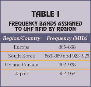
To completely understand the UHF RFID landscape, one must be aware of the various frequencies of operation and the protocols. The frequency bands, assigned internationally by region, are listed in Table 1. While these are the presently known bands, several other countries are in the process of allocating frequencies internationally in the ISM bands for UHF RFID. In addition to frequency bands being assigned, data protocols are also being standardized. This is a tremendous step towards unifying all the disparate systems being used around the world and for helping to drop the overall cost of these systems. Generally, in North America, EPC standards are predominant. These protocols have been named Class 1 and Class 0 (Class 0+ is an addendum of Class 0), each having its own merits. Recently, the second generation of class 1 has been ratified by EPC-Global, known as Class 1 Gen 2; it is expected that the North American industry will converge on this standard. In Europe and internationally, the ISO-18006 standard has been the protocol of choice. Class 1 Gen 2 is presently being considered for adoption into the ISO standards process and it is expected that in the future the EPC and ISO protocols will converge into a single worldwide standard. While it is not necessary to describe the various protocols here, it is important to understand that there are several protocols to be supported, all requiring different reader hardware. The designer must be aware of this and understand the unique specifications of both the protocol and air interface being implemented. All of these issues add to the complexity of the reader design.
RFID readers, otherwise known as transponders, communicate with the tags to program them and read their data. Due to the simplistic nature of the tags, most of the link budget gains come from the reader and antenna, making today’s readers complex, bulky and expensive. The reader transmits at powers up to 4 W EIRP and the reader must be capable of discerning a received signal of the order of –90 dBm, in an environment susceptible to fading, multipath and interference. In addition to this link budget challenge, an ideal reader should be capable of reading several protocols in real time at any of the UHF ISM bands, while frequency hopping to meet regulatory masks. This is quite a challenge for the radio designer. Today’s RFID readers are both simplistic and elegant in nature. The general architecture, as shown in Figure 3, utilizes direct conversion on both the up- and down-links. The transmit chain consists of a modulator of some sort, whether IQ or direct modulation of the carrier. The receive chain is a homodyne receiver with filtering defined in the channel, filtering defined in the baseband or the digital circuitry. When designed to operate for two or more protocols, the readers must be agile, hence they are software-or firmware-controlled radios. The direct conversion architecture can only be realized with a very clean synthesizer and low coupling between the transmit and receive chains. An example of an RFID reader is shown in Figure 4. The SR2200 reader from WJ Communications is indicative of product offerings available for portal applications. The SR2200 is a multi-protocol UHF reader supporting Class 0, 0+ and Class 1, and is Class 1 Gen 2 ready. It has four pairs of transmit and receive connectors to support eight antennas. This type of reader is used at dock doors and around conveyors to quickly and accurately identify large number of items passing through.

Fig. 3 Generic RFID reader of RF architecture.

Fig. 4 WJ Communications’ SR2200 portal reader.
In order for readers to realize mass deployment, the size and cost must decrease over the coming years and their functionality must increase. Today, the supply chain is focused on pallet and carton-level tagging but as item-level tagging becomes practical, pressure will increase on the evolution of reader technology to ensure that applications such as smart shelves are economically practical. This scale of economy can only be accomplished through integration. It is predicted that the RFID reader hardware will evolve in a manner similar to the cellular phone and WiFi hardware. Already, reader form-factors are being reduced based on available semiconductor technology such as the PCMCIA reader engine shown in Figure 5. This engine is very compact and can transmit 1 W on two antenna ports. Unlike the larger portal reader, the PCMCIA reader transmits and receives on the same port, so two fully duplexed antennas may be used. This type of product is suitable for small form factor applications such as handheld readers or RFID label printers. The use of the standard PCMCIA connector also moves the technology into the realm of network devices such as WiFi access points. One could envision a mesh network of RFID readers embedded in WiFi devices to transfer the data to the network. The removal of cabling would greatly simplify the deployment of an RFID system.

Fig. 5 PCMCIA RFID reader engine.
Further reduction in the size and cost of RFID readers can only be accomplished through integration. With the use of highly integrated circuits, one can see how the PCMCIA form factor can be reduced to compact flash (CF) or perhaps secure digital card (SD) format. It is through this evolution that UHF RFID readers will move into low power mobile applications. It is expected that the initial chip sets will consist of three ICs, as shown in Figure 6, following the approach used for early 802.11 chipsets. A digital processor will contain all of the baseband signal processing and control functions. The analog transceiver will perform the translation between the baseband and RF signals, and finally a separate power amplifier will enable flexibility in the design. As technology and design techniques evolve, it may be possible to integrate the entire system onto a complete IC but today the requirements do not lend themselves to a single technology.
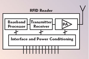
Fig. 6 Chipset-based RFID reader architecture.
The baseband processor will, of course, be implemented in CMOS, the most cost-effective technology for this type of circuit. The transceiver is ideally suited for SiGe BiCMOS, as it enables the synthesizer to be integrated with the demanding linear functions in the signal path. Finally, the power amplifier will most likely be implemented with InGaP HBTs, which have become the industry standard for powers in the 1 W range. It may be possible to integrate the baseband and transceiver functions all in BiCMOS but the cost, risk and performance tradeoffs must be considered. It may also be possible to implement the power amplifier in SiGe, but it will depend on the requirements and capabilities of the selected semiconductor process. An example of transceiver chip architecture is shown in Figure 7. The transceiver includes pulse shaping, frequency synthesis, modulation, automatic level control, up/down conversion and some RF power amplification. This chip, and others currently in development, represents a major step forward toward the fully integrated RFID reader.
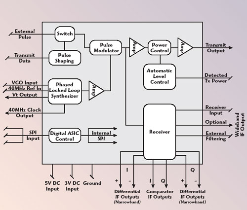
Fig. 7 WJ Communications’ UHF RFID transceiver chip functional block diagram.
UHF passive RFID represents one of the most promising growth prospects in the RF industry in recent years, but there is much research and development to be completed. In this article, semiconductor solutions have been proposed but there are also innovations needed in radio architecture, antenna design, mechanical packaging and signal processing to mention a few, that will drive the RFID industry toward maturity. As the technology evolves toward enabling low power mobile readers, many applications and markets will in turn develop.