Mobile communication systems currently use multi-carrier/multi-channel schemes for effective use of the frequency spectrum resources. The intermodulation has a serious impact on these communication systems in terms of adjacent channel interference, resulting in an increase of bit error rates. As the power amplifier operates close to the saturation region to achieve high efficiency and high output power, the degradation in linearity becomes significant. A “back-off” mode of operation can improve the linearity, but results in lower efficiency and output power. In power amplifier design, there is a tradeoff between the degree of linearity and the levels of efficiency or output power, for a constant power supplied to the amplifiers. A technique to reduce the nonlinearity of the power amplifier is the only viable solution. Various linearization methods have been reported, including feed-forward, feedback, predistortion, LINC (linear amplification with nonlinear components), CALLUM (combined analog locked loop universal modulator), EER (envelope elimination and restoration) and so forth.1,2 The costs of implementation, bandwidth and efficiency are different according to the method used.
Predistortion is the simplest form among linearization methods, although the improvement of linearity is not as great as that of the feed-forward method. A digital predistortion3 and a method using the frequency up-conversion operation of a microwave mixer4 have been proposed. In this article, a new predistortion scheme is introduced, which generates the predistortion signal using the subtraction of the PA output signal from the original input signal. This method offers a compact circuit size and a simple means to generate and control the predistortion signal. Also, the drawbacks of the feedback linearization method are avoided; high gain and low feedback are obtained for the pure input signal, whereas a high feedback is obtained for the IMD signal. The drawback of the present scheme, however, is that it requires precise matching of phase and amplitude in the IMD extraction circuit.
Feedback Predistortion
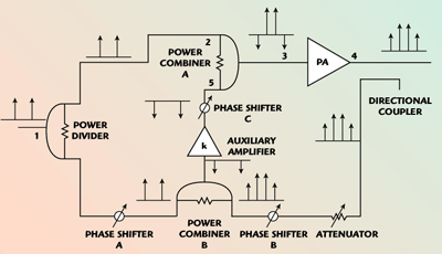
A simplified schematic of a feedback predistortion system is shown in Figure 1. The predistortion circuit consists of a power divider, two power combiners, three variable phase shifters, a variable attenuator, a directional coupler and an auxiliary amplifier. The input signal is divided into two parts, one to the power combiner A, where the original signal is combined with the predistortion signal and then fed to the power amplifier, and the other to the power combiner B, where a fraction of the PA’s output signal is subtracted from the original input signal and the predistortion signal is generated. The directional coupler takes a sample of the main PA output signal, the signal passes through the attenuator and phase shifter B, and is then fed to the power combiner B where the original signal is subtracted. After this subtraction process, a predistortion signal is generated, which contains the distortion information of the main power amplifier. Ideally, none of the original signal energy will remain. The predistortion signal is amplified linearly, phase-shifted and then fed to the power combiner A. The main PA amplifies the original input signal and the predistortion signal; the output signals include the amplified original signal, its third-order intermodulation signal and the amplified predistortion signal, which is opposite in phase to the intermodulation signal. Consequently, the IM3 is improved.

Fig. 1 Schematic of the feedback predistortion system,
Assuming the main amplifier is memoryless, its output can be expressed by the power series expansion5
![]()
where k1 and k3 are the power series coefficients that characterize the nonlinearity of the main amplifier. Assuming that the power divider is an ideal 3 dB hybrid, then the output of the divider, V2(t), for an input original signal, V1(t), is given by

According to Equation 1, the output of the main PA is
![]()
where
V4(t) = output of the PA
V3(t) = input signal of the PA
Supposing that the predistortion signal is
![]()
where
k = gain of the auxiliary amplifier
x = a coefficient
Then the output signal of the main PA is

If only the third-order power series items are taken into account, then

By using Equation 4, the predistortion signal can be written as

where
?1 = insertion loss coefficient of feedback circuit (including the directional coupler, attenuator and phase shifter)
?2 = insertion loss coefficient of the phase shifter A
After expansion, some results are derive

According to Equations 2, 6 and 8, the output signal of the main PA can be expressed as

The IP3 and its improvement can be written as (R = 50 ?)6

The third-order IMD can be written as6


where
Vi1 = input voltage of the PA with predistorter
Vi0 = input voltage of the PA without predistorter for the case of same value of output power
Analyzed and Experimental Results
To validate the proposed feedback predistortion method, an experimental PA was fabricated. A Motorola MHL9838 device was used as the main PA, whose gain and P1dB are 31 dB and 39 dBm, respectively. A Motorola MBC13916 device was used as the auxiliary amplifier, whose gain is approximately 7.29 dB (Vcc = 3.0 V). The variable phase shifter and attenuator are Skyworks PS088-315 and AV104-12 devices, respectively. The power divider and combiners are Skyworks PD09-12 devices.
From the parameters of MHL9838, its power series coefficients6 can be obtained as
k1 = 35.48 k3 = –6.486
The nonlinear model of the PA without predistorter can be written as

If a2 = 0.158 (–8 dB), with the predistorter, the nonlinear model can be written as
![]()
The improvement of IP3 and IM3, (the output power of a single frequency is 30 dBm) is
?IP3 = 8.6 (dBm)
?IM3 = 5.2 (dBm)
when ?2 = 0.63 (–2 dB), DIM3 = 12.5 (dBm).
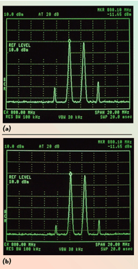
The two-tone test frequencies are approximately 882 and 880 MHz, with output powers of 30 dBm each. Figures 2 and 3 show the comparison between the nonlinear characteristics of the HPA with and without the feedback predistorter. When ?2 = –8 dB, IM3 is approximately –34 dBm in the case without the predistorter and approximately –39 dBm with the predistorter. Hence, the IM3 improvement is about 5 dB. In the case where ?2 = –2 dB, IM3 is approximately –46 dBm with the predistorter. The IM3 improvement is about 12 dB. The experimental results agree quite well with the analyzed results.

Fig. 2 Comparison of the nonlinear characteristics of the PA ( ?2 =-8 dB) (a) without predistorter and (b) with predistorter.

Fig. 3 Comparison of the nonlinear characteristics of the PA ( ?2 =2 dB) (a) without predistorter and (b) with predistorter.
Conclusion
In this article, a feedback predistortion scheme is presented and analyzed. The experimental results agree quite well with the theoretical results, which validates this approach. The proposed method uses the PA output signal to generate the predistortion signal, then feeds it back to the input of the PA, whose output signal is opposite in phase to the distortion of the original signal, so the distortion is improved. This method makes it very easy to generate the predistortion signals and control them, and the adjustment sensitivities of the signal and error cancellation loops are reduced by the feedback loop.
References
1. S.C. Cripps, Advanced Techniques in RF Power Amplifier Design, Artech House Inc., Norwood, MA, 2002.
2. P.B. Kenington, High Linearity RF Amplifier Design, Artech House Inc., Norwood, MA, 2000.
3. F. Zavosh, M. Thomas, C. Thron, T. Hall, D. Artusi, D. Anderson, D. Ngo and D. Runton, “Digital Predistortion Techniques for RF Power Amplifiers with CDMA Application,” Microwave Journal, Vol. 42, No. 10, October 2004, pp 22–50.
4. Y.C. Jeong, Y. Kim and C.D. Kim, “Design of a Predistortion HPA Using a Frequency Up-conversion Mixing Operation,” Microwave Journal, Vol. 47, No. 10, October 2004, pp. 114–124.
5. T.T. Ha, Solid Microwave Amplifiers Design, Publishing House of Electronics Industry, Beijing, PRC, 1988.
6. Y.X. Zhang, RF Simulate Circuit, Publishing House of Electronics Industry, Beijing, PRC, 2002.
Lin Qiang received his MEng degree in communication engineering from Huazhong University of Science and Technology in 1998.
Zhang Zu Ying graduated from Qinghua University, PRC, in 1963, and is currently a professor at Huazhong University of Science and Technology.
Guo Wei is a professor at Huazhong University of Science and Technology.
