A spiral is a very important form of planar or multilayer inductor or transformer. Previous designs of spiral components, however, have relied heavily on approximate quasi-static models and verification using electromagnetic field solvers. Recently, an application-specific graphical user interface has been created for use with the IE3D high performance EM Simulation and Optimization software to facilitate the design of spiral circuit components.
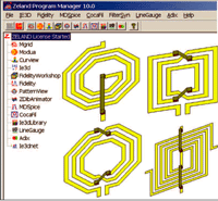
SpiralSyn is a spiral analysis and synthesis module integrated with the IE3D Library. It performs electromagnetic analysis and synthesis using the IE3D field solver, with a graphical user interface. SpiralSyn creates spiral objects and exports them to IE3D. It can also be invoked from a spiral component layout.
SpiralSyn currently handles seven spiral structures from inductors to transformers, as well as interdigital and metal-insulator-metal (MIM) capacitors. The list of inductors and transformers includes single-ended rectangular and differential rectangular spiral inductors, single-ended octagonal and differential octagonal spiral inductors, double-layer rectangular spiral inductors, partly bifilar rectangular spiral transformers, and entirely bifilar rectangular spiral transformers.
Experimental Verification

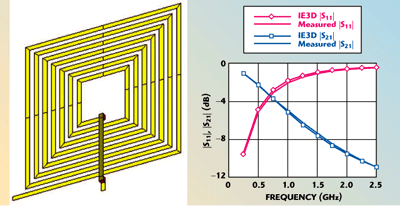
Fig. 1 Simulated and measured response of a rectangular spiral inductor.
SpiralSyn was used to analyze several spiral structures that had available measured data to verify its accuracy. Figure 1 shows the layout and comparison of simulated and measured S-parameters1 of a rectangular spiral inductor. Figure 2 shows the physical layout and compares simulated S-parameters with measured data2 of a rectangular spiral transformer. It can easily be seen that the SpiralSyn simulations are in excellent agreement with the corresponding measurements in the two examples.

Fig. 2 Simulated and measured response of a rectangular spiral transformer.
A Design Example
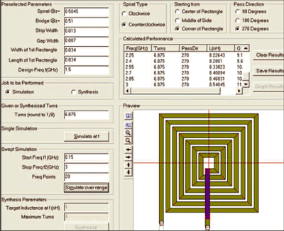
A design example of a rectangular spiral inductor using SpiralSyn is presented to demonstrate the software’s usefulness. The case for analysis is a 6.875-turn spiral on 4.5 ?m thick SiO2 on a 500 mm thick silicon substrate. The graphical user interface of SpiralSyn is so simple that entering the dimensions and parameters of the spiral, selecting the options and starting the simulation is all that is necessary to perform the analysis. In this case, SpiralSyn completed the analysis in approximately one minute using a 2.5 GHz Pentium 4 machine. The analysis results are shown in Figure 3.

Fig. 3 SpiralSyn analysis of a spiral inductor on silicon.
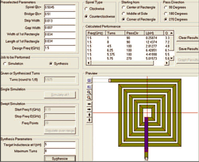
The synthesis example uses the same layer structure and trace parameters, although the synthesis target is a 5 nH inductance at 1.5 GHz. SpiralSyn determined it to be a 5.75-turn spiral with an inductance value of 5.01 nH. Figure 4 shows the results of that synthesis.

Fig. 4 SpitalSyn synthesis of a spiral inductor on silicon.
Conclusion
An IE3D Library module for spirals has been described and verified through comparisons with measurements. SpiralSyn performs spiral synthesis based on accurate electromagnetic simulation and is a useful tool in RFIC design.
References
1. D.M. Krafcsik and D.E. Dawson, “A Closed-form Expression for Representing the Distributed Nature of Spiral Inductors,” IEEE Microwave and Millimeter-wave Monolithic Circuits Symposium Digest, Baltimore, MD, June 4–5, 1986, pp. 87–92.
2. E. Frlan, et al., “Computer-aided Design of Square Spiral Transformers and Inductors,” IEEE International Microwave Symposium Digest, Long Beach, CA, June 13–15, 1989, pp. 661–664.
Zeland Software Inc.,
Fremont, CA
(510) 623-7162,
www.zeland.com
