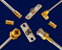
With today’s emphasis on small size and light weight, the coaxial RF connector is rapidly becoming one of the larger components in a modern electronic system. To help counter that trend, AEP has introduced a new microminiature SMP connector series that combines high performance and high frequency capability with small size, and adds blind mating to the mix as well. Three detent configurations in the mating end provide a range of mating and retention forces to match specific applications.
Both the straight and the right-angle SMP connectors have gone through an extensive design phase to optimize electrical performance. Currently there are designs for both 0.047" and 0.086" semi-rigid cable. The frequency range for this new series of connectors is DC to 40 GHz, and the cable connectors include an integrated EMI/anti-rock ring to reduce RF leakage and maintain mating alignment. The 0.086" straight female design exhibits very little insertion loss and a VSWR of better than 1.20 to 40 GHz. The right-angle version exhibits slightly more loss than the straight connectors and the 0.086" version currently has a typical VSWR of better than 1.20 to 36 GHz. Figure 1 shows typical performance vs. frequency for a straight female SMP connector direct soldered to 0.086" semi-rigid cable and a right-angle female (soldered center contact) direct soldered to similar 0.086" cable.

Fig. 1 VSWR performance for a straight and right-angle female SMP connector soldered to 0.086" semi-rigid cable.
AEP right-angle connectors have stayed with the proven bifurcated slot on the connector center contact. This slot allows for the cable center wire to be soldered to the contact providing lower contact resistance, a stronger joint during vibration and a longer service life by eliminating corrosion.
SMP body components are stainless steel or beryllium copper to ensure rugged performance and a service life of over 1000 mating cycles (dependent on the mating type) with no degradation of performance. The body finish is either gold plated or passivated, center contacts are gold plated and the insulators are PTFE for consistent electrical performance through a wide temperature range.
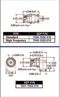
Current configurations include straight and right-angle cable connectors, panel shrouds for use with hermetic seals, several lengths of female-to-female “bullet” adapters and panel-mounted cable connectors (including snap-in types). Figure 2 shows mechanical outlines for both the straight and right-angle female cable connectors for 0.086" semi-rigid cable.

Fig. 2 SMP straight (top) and right-angle (bottom) female cable connectors for 0.086" semi-rigid cable.
One of the advantages of these connectors is in blind-mate applications with multiple connector pairs. SMP connectors allow for as much as 0.010" radial and 0.010" axial misalignment of mating connectors without damage when engaging. An optional “Catcher’s Mitt” configuration can extend the radial misalignment tolerance to 0.020".
A new eight-page SMP brochure is available from AEP that lists specifications, application notes and assembly tooling. The brochure, along with pricing and availability information, can be downloaded from the company’s Web site.
Applied Engineering Products (AEP),
New Haven, CT
(203) 776-2813,
www.aep.com
